
Light weight composite armor with structural strength

a composite armor and structural strength technology, applied in the field of passive ballistic armor, can solve the problems of limited fracture toughness and damage tolerance, large weight penalty, and parasitic ceramics to the vehicle structure, and achieve the effects of increasing penetration resistance, reducing residual protection, and increasing performan

Inactive Publication Date: 2015-12-24
NIELSEN FRANK
View PDF1 Cites 3 Cited by
  • Summary
  • Abstract
  • Description
  • Claims
  • Application Information

AI Technical Summary

Benefits of technology

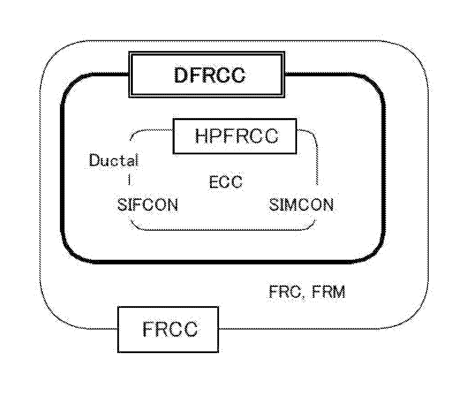
The patent text describes the use of a laminate system composed of a hard frontal plate and a metallic or polymer composite backing to defeat lethal projectiles. This system works by breaking the projectile's energy with the hardness of the frontal plate and catching the residinals with the backing. Both ceramics and metals have their advantages and limitations, and the text proposes the use of FRCC (fiber-reinforced cement composite) around the ceramics to improve their performance and impede their disintegration when hit by projectiles. The technical effect of this is that the FRCC reinforces the ceramics, making them stronger and more durable against armor-piercing threats.

Problems solved by technology

Facial ceramics are most effective in this type of application, but have limited fracture toughness and damage tolerance; thus the ceramic is parasitic to the vehicle structure.
However, they have a large weight penalty and are not as efficient at stopping armor-piercing threats.
Ceramics are extraordinarily hard, strong in compression, light weight and brittle, making them efficient at eroding and shattering armor-piercing threats, but not as effective at withstanding multiple hits.
This decreases the ability of the projectile to defeat the armor system.

Method used


Image

  • Light weight composite armor with structural strength
  • Light weight composite armor with structural strength
  • Light weight composite armor with structural strength

Examples


Embodiment Construction

[0163]With reference now to the figures of certain preferred embodiments in detail, it is stressed that the particulars shown are by way of example and for purposes of illustrative discussion of the preferred embodiments of the present disclosure only, and are presented in the cause of providing what is believed to be the most useful and readily understood description of the principles and conceptual aspects of the present disclosure. In this regard, no attempt is made to show structural details of the present disclosure in more detail than is necessary for a fundamental understanding of the present disclosure. Only a few examples of how the composite armor structure can be configured in different shapes, sizes and thicknesses, and in different configurations, and how the encapsulated armor-grade material can be configured and arranged in different spacious patterns are shown here.

[0164]The description taken with the drawings makes it apparent to those skilled in the art how the sev...


PUM

PropertyMeasurementUnit
volume fractionaaaaaaaaaa
fracture energyaaaaaaaaaa
flexural tensile strengthaaaaaaaaaa

Abstract

Future fighting vehicles will require lighter, stronger and more space efficient armor for better protection, better survivability and better mobility.The invented lightweight armor component consists of armor-grade material (2), such as ceramic, encapsulated in fiber reinforced cementitious composite (FRCC) (1). The encapsulation FRCC pre-stress the armor-grade material.The resulting armor component of the present disclosure provides excellent ballistic protection against most types and sizes of Kinetic Energy (KE) threats and Chemical Energy (CE) threats.The armor component has low areal density, reduced damage area, improved multi-hit capability, flexible design and also provides high structural strength. It furthermore has the advantage, that it can be formed in virtually any shape.The present disclosure results in superior ballistic characteristics of an armor component. An object of the present disclosure is to increase penetration resistance of especially ceramic based armor, while lowering system weight.

Description

FIELD AND BACKGROUND OF THE INVENTION[0001]The present disclosure relates generally to passive ballistic armor for military and civilian use, and in particular, to lightweight composite armor structure with very strong structural strength based on a multi-material composite for absorbing and limiting the transfer of impact energy from most types and sizes of kinetic energy (KE) threats and chemical energy (CE) threats.[0002]The present disclosure relates especially to ballistic protection for use in military vehicles of different types and other moving and stationary military platforms, or for use in permanent or temporary protection of different types in buildings or other fixed or mobile installations. The ballistic protection according to the present disclosure can be employed as protection against different types and sizes of low-velocity or high-velocity armor ballistic threats, such as armor piercing projectiles or threats based on chemical energy.[0003]It is an object of the ...

Claims


Application Information

Patent Timeline
Patent Type & Authority Applications(United States)
IPC IPC(8): F41H5/04
CPCF41H5/0428F41H5/0414F41H5/0471F41H5/0492
Inventor NIELSEN, FRANK
Owner NIELSEN FRANK
Learn More