Bearing anomaly detection and location

a technology for bearing anomalies and location, applied in the direction of machines/engines, digital computer details, instruments, etc., can solve the problems of affecting machine functioning, complex task of analysing the complete series of indicators to determine the condition of the engine, and high number of indicators that must be monitored to obtain an overall picture of the engine condition

Active Publication Date: 2005-06-02
ROLLS ROYCE PLC
View PDF10 Cites 57 Cited by
  • Summary
  • Abstract
  • Description
  • Claims
  • Application Information

AI Technical Summary

Benefits of technology

[0036] So, for example, it is often the case that the onset of a bearing problem or failure manifests itself in small changes to a number of condition indicators which individually, however, remain in their respective allowable ranges. The “look up table” approach, which is only able to sense gross shifts in individual parameters, would fail to recognise that a problem or failure had occurred. In contrast, when the condition signature is predicted from a model defining one or more inter-dependencies between the condition indicators the several small changes in the condition indicators may have the cumulative effect of driving the condition signature outside the normal boundary in N-dimensional space.

Problems solved by technology

However, particularly with complex machinery such as gas turbine engines, the number of indicators that must be monitored to obtain an overall picture of the engine's condition can be high.
This in turn means that the task of analysing the complete series of indicators to determine the condition of the engine can be a complex one.
Defects in bearing surfaces can affect machine functioning and catastrophic bearing failure can even compromise safety.

Method used


Image

  • Bearing anomaly detection and location
  • Bearing anomaly detection and location
  • Bearing anomaly detection and location

Examples


Embodiment Construction

[0068] The first embodiment described below is an example of a methodology for locating bearing anomalies (such as inner / outer bearing track defects, cage defects, rolling element defects and squeeze-film bearing anomalies) in a gas turbine engine.

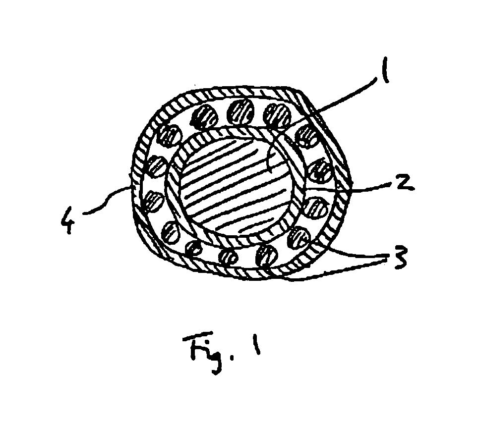
[0069]FIG. 1 shows a schematic transverse cross section of the high pressure (HP) shaft 1 of the gas turbine. The shaft is located by a circular bearing which comprises an inner race 2, caged rolling elements 3 (cage not shown) and outer race 4. A defect can exist in either of the races or the cage and rolling elements.

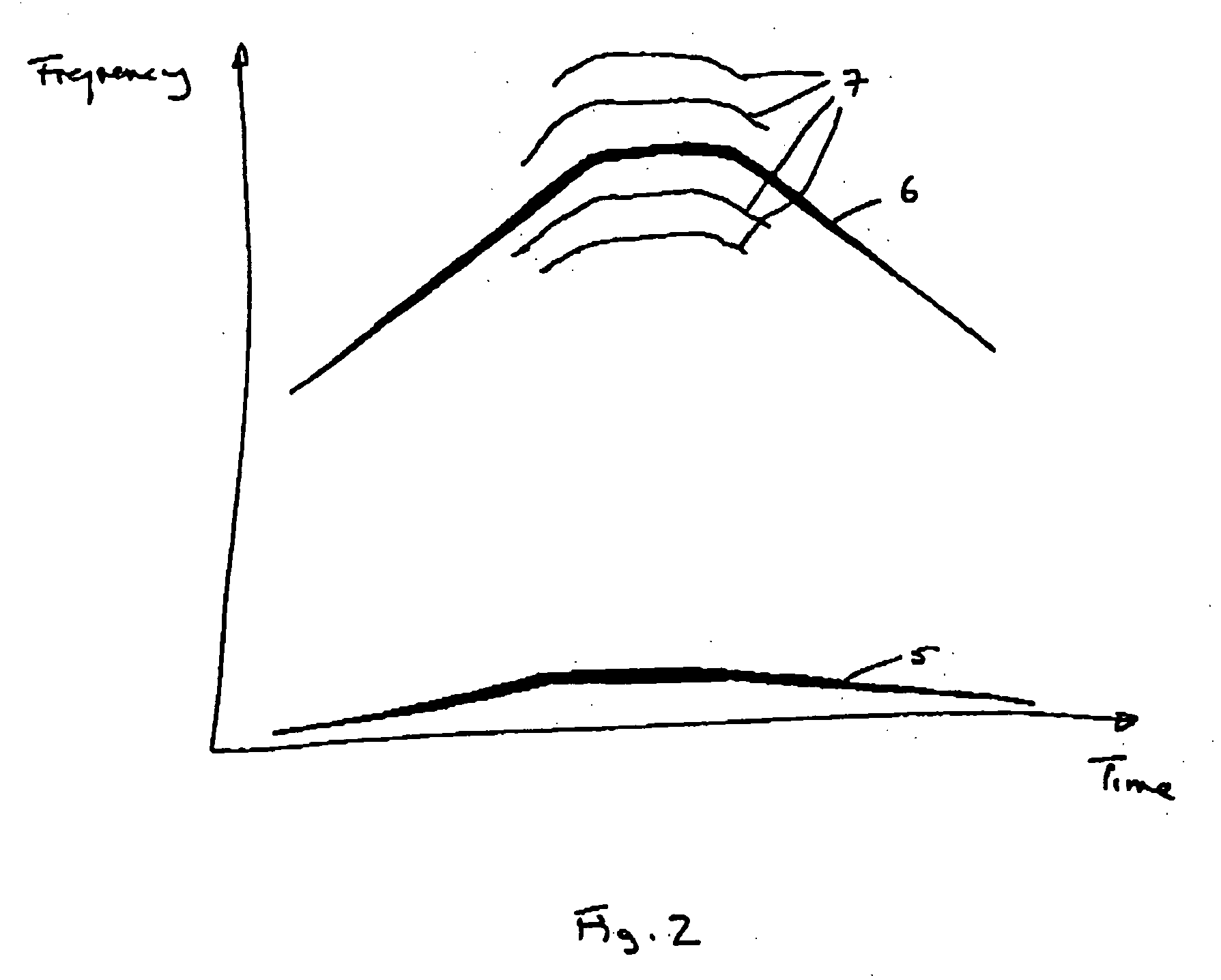
[0070]FIG. 2 shows a schematic plot of frequency against time for the fundamental HP tracked order 5 (which is also the HP shaft rotation frequency) and a higher frequency nov 1 tracked order 6. Both tracked orders are measured by vibration sensors attached to the engine. The upward and downward slopes of the tracked orders respectively correspond to an increase and decrease in engine speed, and the darkness of each tracke...


PUM


Abstract

A method for monitoring the health of a system comprises performing at each of a plurality of times the steps of: constructing a condition signature (30) from a plurality of condition indicators including (a) a plurality of vibration measurements acquired from the system or (b) one or more vibration measurements and one or more performance parameter measurements acquired from the system; predicting a normal signature (32) from a model defining one or more inter-dependencies between said condition indicators, the normal signature corresponding to the condition signature for a healthy system; comparing the condition signature with the normal signature; and registering an event if the condition signature differs from the normal signature by more than a predetermined threshold.

Description

FIELD OF THE INVENTION [0001] This invention relates to methods and data processing systems for detecting and locating bearing anomalies. The methods and data processing systems of the invention are particularly, although not necessarily exclusively, suitable for detecting bearing anomalies in rotating machinery such as for example gas turbines, spark ignition and compression ignition internal combustion engines, and other types of power plant. BACKGROUND [0002] In order to determine the condition of machinery, it is normal to monitor and analyse a series of measurable “condition indicators” which themselves reflect aspects of the condition of the machine. This allows machine deterioration and / or problems to be detected and, if necessary, addressed at an early stage. [0003] However, particularly with complex machinery such as gas turbine engines, the number of indicators that must be monitored to obtain an overall picture of the engine's condition can be high. This in turn means tha...

Claims


Application Information

Patent Timeline
Patent Type & Authority Applications(United States)
IPC IPC(8): G01M13/04G06F19/00
CPCG01N2291/2696G01M13/045
Inventor ASTLEY, KENNETH RICHARDANUZIS, PAULKING, STEPHEN PETERKING, DENNIS MAXWELL
Owner ROLLS ROYCE PLC
Why Eureka
Try Eureka