Device for testing at least one pressure sensor

Active Publication Date: 2005-06-09
ROBERT BOSCH GMBH
View PDF12 Cites 19 Cited by
  • Summary
  • Abstract
  • Description
  • Claims
  • Application Information

AI Technical Summary

Benefits of technology

[0002] The device according to the present invention for testing at least one pressure sensor has the advantage that now, in addition, as a function of the pressure signal that the device exerts on the pressure sensor, the tightness (leakproofness) of the at least one pressure sensor is checked. A pressure sensor, particularly for side impact sensing, is usually constructed in such a way that it has a pressure inlet channel in the housing, which supplies the environmental pressure to a diaphragm that is mounted, for instance, in a premold housing. In order to be protected from water vapor, and especially salt water vapor, the diaphragm is fully sealed using a gel seal. In order not to let the water vapor penetrate into the pressure housing beyond the pressure inlet channel and the gel seal, the pressure inlet channel is typically sealed at the housing around the diaphragm. The sealing may be implemented, for example, by pressing in a silicone pad (washer) between the inlet channel and the sensor housing. Whether this seal has a certain tightness is an important functional parameter. In an advantageous manner, using the checking procedure, one may test in one step both the operativeness of the pressure sensor with respect to its pressure measuring and its tightness.
[0004] However, it is alternatively also possible to check the tightness using a dynamic signal. For, the dynamic signal shows, in the response signal of the pressure sensor, a lesser amplitude if there is a leak in the pressure sensor. This measurement is suitable especially for greater leaks, whereas the measurement using static pressure is suitable for fine leaks. It follows from this that a combination of these two measurements is very advantageous.

Problems solved by technology

For, the housing of a pressure sensor also has welded seams, which could possibly lead to a lack of tightness.
Other leaks in the housing of the pressure sensor are not able to be detected like that.

Method used


Image

  • Device for testing at least one pressure sensor
  • Device for testing at least one pressure sensor
  • Device for testing at least one pressure sensor

Examples


Embodiment Construction

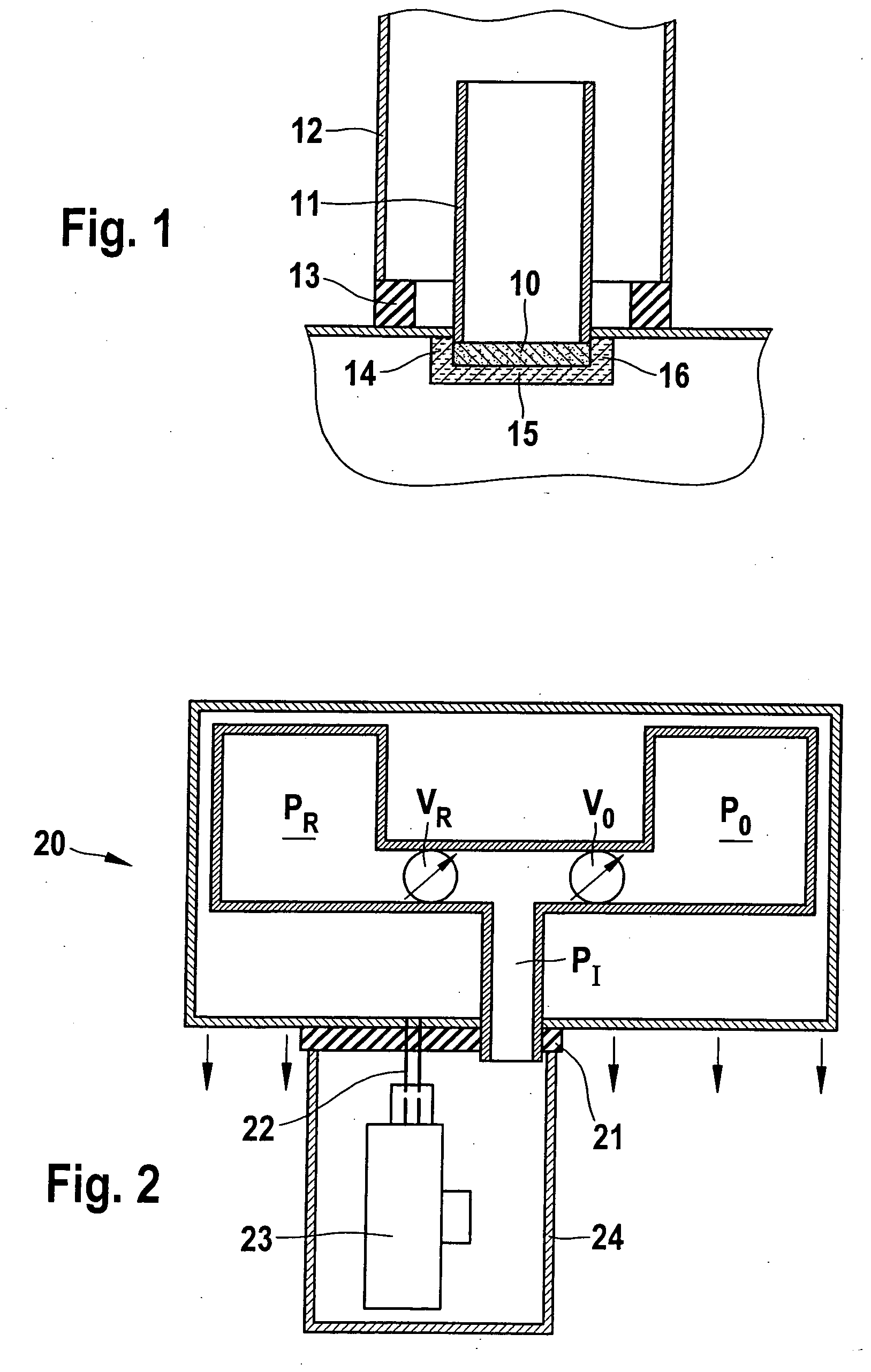
[0013] Pressure sensors are increasingly being used for impact sensing. In this context, the pressure sensors are frequently installed in lateral cavities of a vehicle, so that if there is an impact upon the wall of the cavity, based on the rapid deformation and thus volume reduction, one may measure a brief adiabatic pressure increase, in order thereby to have a rapid sensing method for a side impact. These pressure sensors may be produced micromechanically. Usually this involves micromechanics based on silicon. In this context, using micromechanical technology, a diaphragm is produced, about which an evaluation circuit is provided. The evaluation circuit having a measuring amplifier generates the measuring signal which then, using a transmitter module, is transmitted to a control unit, which also activates means of restraint, as a function of this signal. The diaphragm of the pressure sensor, as represented above, is exposed to the medium in the lateral cavity. In order to protect...


PUM


Abstract

A device for testing at least one pressure sensor, by applying a pressure signal, the device testing the operativeness of the pressure sensor as a function of the pressure signal. In addition, it is provided that the device tests the tightness of the pressure sensor as a function of the pressure signal.

Description

BACKGROUND INFORMATION [0001] A device for checking pressure sensors is known from German Patent Application No. DE 100 00 133. In this context, the pressure sensors are checked with respect to their function. The device exerts either a static or a dynamic pressure on the pressure sensor and measures its reaction with the aid of its electrical signal. The operativeness of the pressure sensor is verified with the aid of this reaction. The checking is done after final assembly. SUMMARY OF THE INVENTION [0002] The device according to the present invention for testing at least one pressure sensor has the advantage that now, in addition, as a function of the pressure signal that the device exerts on the pressure sensor, the tightness (leakproofness) of the at least one pressure sensor is checked. A pressure sensor, particularly for side impact sensing, is usually constructed in such a way that it has a pressure inlet channel in the housing, which supplies the environmental pressure to a ...

Claims


Application Information

Patent Timeline
IPC IPC(8): G01L27/00
CPCG01L27/007
Inventor OHL, CHRISTIANSCHATZ, OLIVERADAM, BORIS
Owner ROBERT BOSCH GMBH
Why Eureka
Try Eureka