Water filler for water tank

Active Publication Date: 2005-06-09
HUANG SO MEL
View PDF14 Cites 10 Cited by
  • Summary
  • Abstract
  • Description
  • Claims
  • Application Information

AI Technical Summary

Benefits of technology

[0007] Another objective of the present invention is to provide a water filler having a quick water stop function.
[0008] A further objective of the present invention is to pr

Problems solved by technology

However, the water level in the water tank 4 is lifted slowly, so that the second end 161 of the press plate 16 cannot be moved rapidly to

Method used


Image

  • Water filler for water tank
  • Water filler for water tank
  • Water filler for water tank

Examples


Embodiment Construction

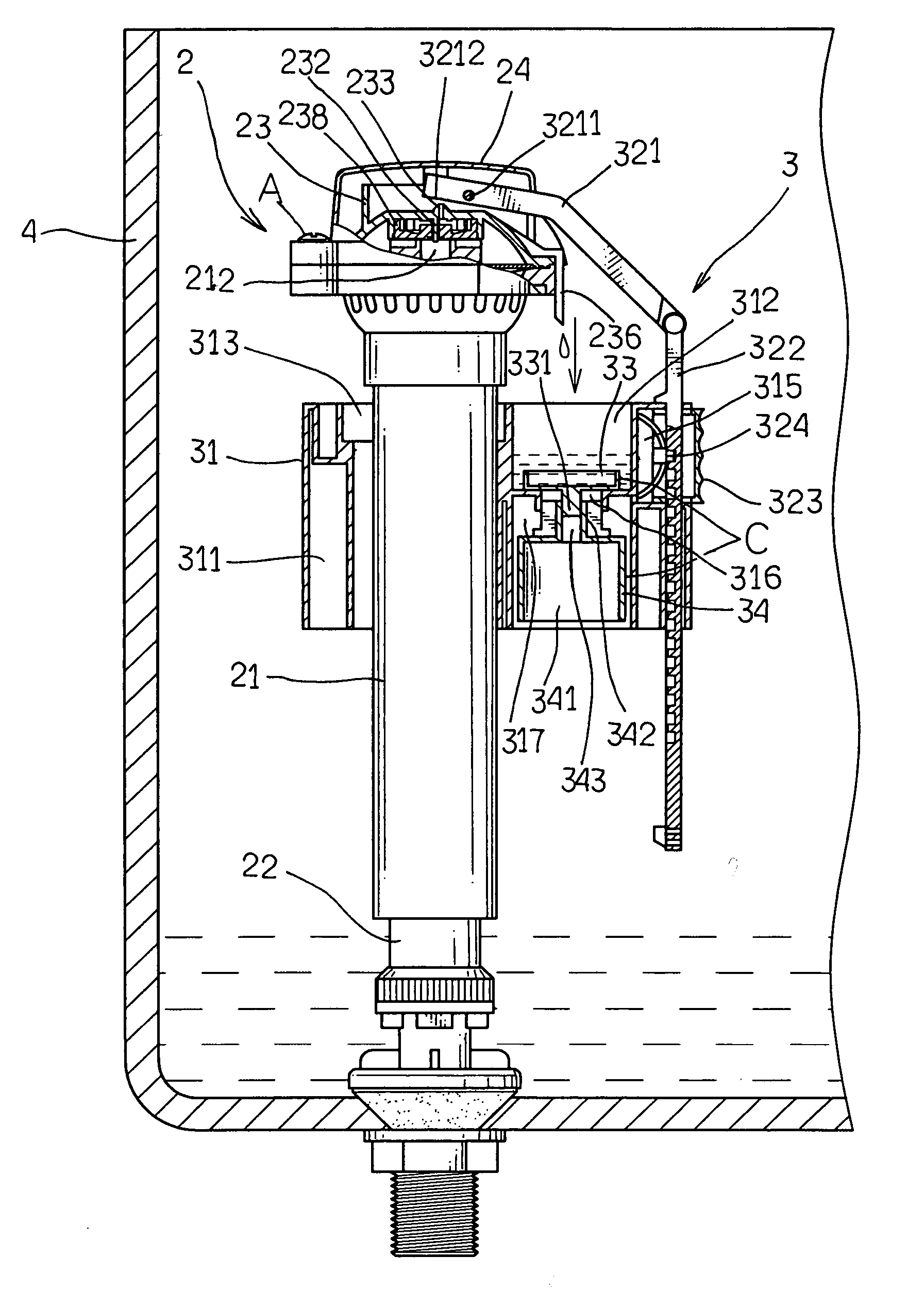
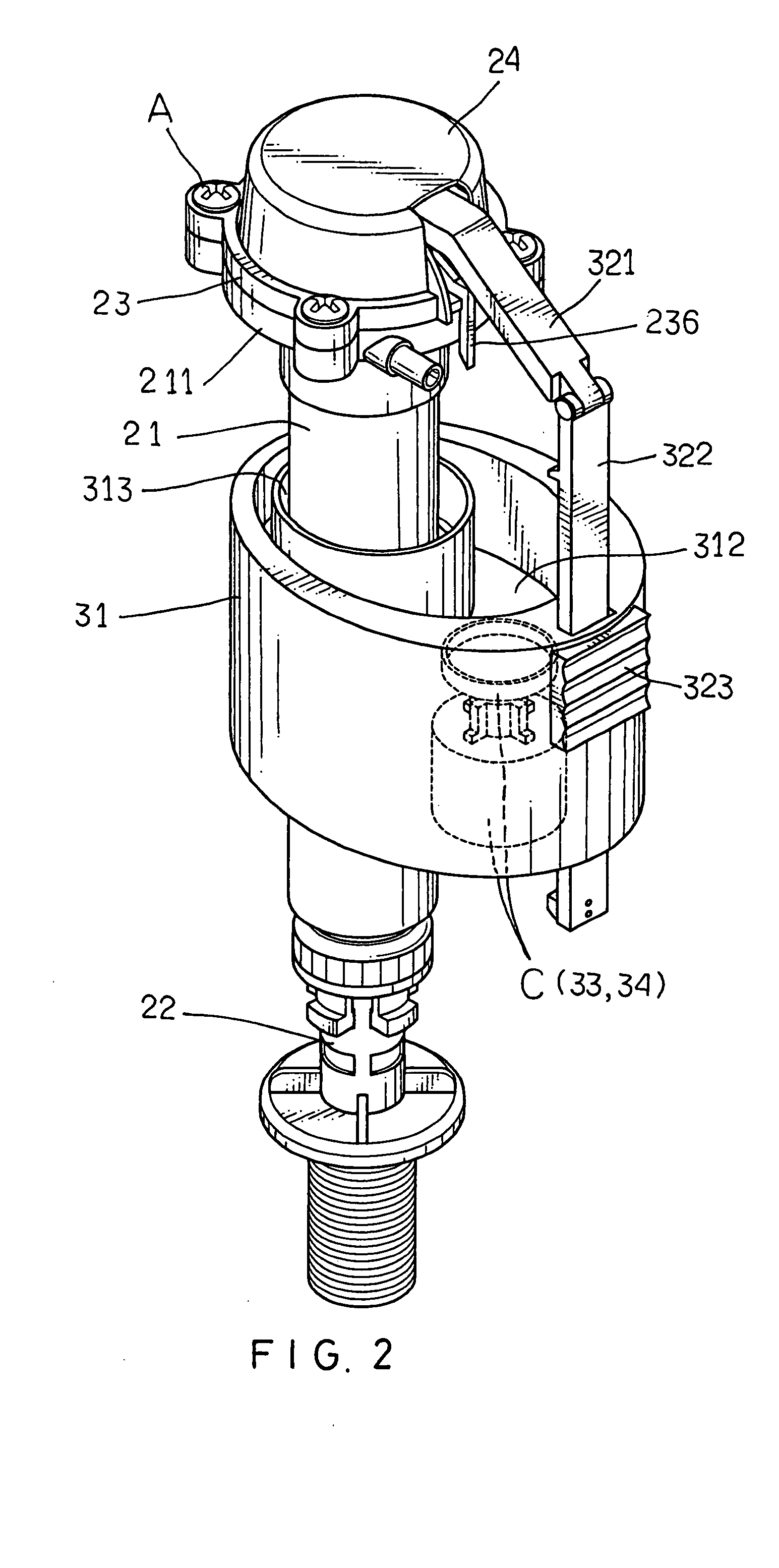
[0029] Referring to the drawings and initially to FIGS. 2-5, a water filler in accordance with the preferred embodiment of the present invention is mounted in a water tank 4 and comprises a water filling device 2, and a regulating device 3.

[0030] The water filling device 2 includes an inner filling tube 22, an outer filling tube 21, an upper cover 23, and an outer cover 24.

[0031] The inner filling tube 22 is mounted in the water tank 4 to supply the water into the water tank 4.

[0032] The outer filling tube 21 is mounted on the inner filling tube 22 and has an upper end having a center formed with a water inlet 212 communicating with the inner filling tube 22 and a periphery formed with a flange 211.

[0033] The upper cover 23 is mounted on the flange 211 of the outer filling tube 21 by a plurality of screws A. The upper cover 23 has a top formed with a water outlet 233 and has an inner wall formed with a chamber 231 communicating with the water outlet 233. A sealing gasket 238 is ...


PUM


Abstract

A water filler includes a water filling device, and a regulating device. The water filling device includes an inner filling tube, an outer filling tube, and an upper cover. The regulating device includes a floating barrel, a sliding barrel, a water support disk, and an adjusting unit. Thus, the floating barrel is lifted instantaneously and rapidly to stop the water filling action exactly and actually, thereby saving the water source. Thus, the water filler has a quick water stop function.

Description

BACKGROUND OF THE INVENTION [0001] 1. Field of the Invention [0002] The present invention relates to a water filler for a water tank, and more particularly to a water filler having a quick water stop function. [0003] 2. Description of the Related Art [0004] A conventional water filler 1 in accordance with the prior art shown in FIG. 1 is mounted in a water tank 4 and comprises an inner filling tube 11 mounted in the water tank 4 to supply the water into the water tank 4, an outer filling tube 12 mounted on the inner filling tube 11 and having an upper end formed with a water outlet 121 communicating with the inner filling tube 11, a floating barrel 13 movably mounted on the outer filling tube 12, a support bar 14 adjustably mounted on the floating barrel 13 by a control unit 15, and a press plate 16 having a first end pivotally mounted on an upper end of the support bar 14 and a second end 161 pivotally mounted on the upper end of the outer filling tube 12. Thus, when the water leve...

Claims


Application Information

Patent Timeline
IPC IPC(8): E03D1/32F16K31/18F16K31/26F16K33/00
CPCE03D1/32F16K33/00F16K31/265Y10T137/741Y10T137/7413Y10T137/7433Y10T137/7472
Inventor HUANG, SO-MEL
Owner HUANG SO MEL
Why Eureka
Try Eureka