Airflow control devices based on active materials

a technology of active materials and airflow control, which is applied in the direction of air-flow influencers, roofs, propulsion parts, etc., can solve the problems of not adapting to the airflow relative to the vehicle cannot be adjusted to better suit the changing driving conditions, and the downforce can affect the stability and handling of the vehicl

Active Publication Date: 2005-06-09
GM GLOBAL TECH OPERATIONS LLC
View PDF45 Cites 75 Cited by
  • Summary
  • Abstract
  • Description
  • Claims
  • Application Information

AI Technical Summary

Benefits of technology

[0006] Disclosed herein are airflow control devices for vehicles. In one embodiment, the vehicle comprises an active fluid control device cooperatively positioned in the vehicle for selectively controlling air flow to a component, wherein the active fluid control device comprises a body portion having at least one surface; and an active material in operative communication with the at least one surface of the body portion, the active material being operative to change at least one attribute in response to an activation signal, wherein an airflow across the active fluid control device changes with the change in the at least one attribute of the active material

Problems solved by technology

Vehicle lift and downforce can affect vehicle stability and handling.
Such devices generally do not adapt as driving conditions change, thus the airflow relative to the vehicle cannot be adjusted to better suit the changing driving conditions.
Vehicle designers are faced with the challenge of controlling the airflow while maintaining sufficient ground clearance to avoid contact with and damage by parking ramps, parking blocks, potholes, curbs and the like.
Further, inclement weather, such as deep snow slush or rainfall, can damage the device and / or impair vehicle handing.
However, such actuators generally require additional components such as pistons, motors, solenoids and / or like mechanisms for activation, which increase the complexity of the device often resulting in an increased number of failure modes as well as increased maintenance and manufacturing costs.

Method used


Image

  • Airflow control devices based on active materials
  • Airflow control devices based on active materials
  • Airflow control devices based on active materials

Examples


example 1

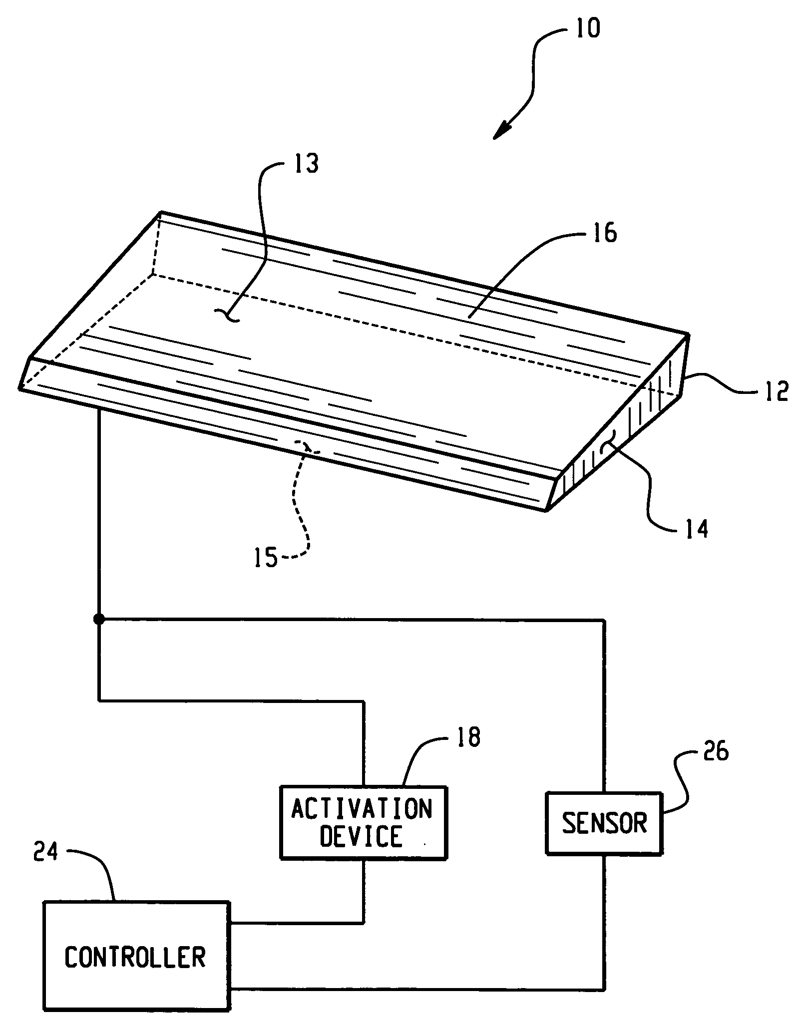
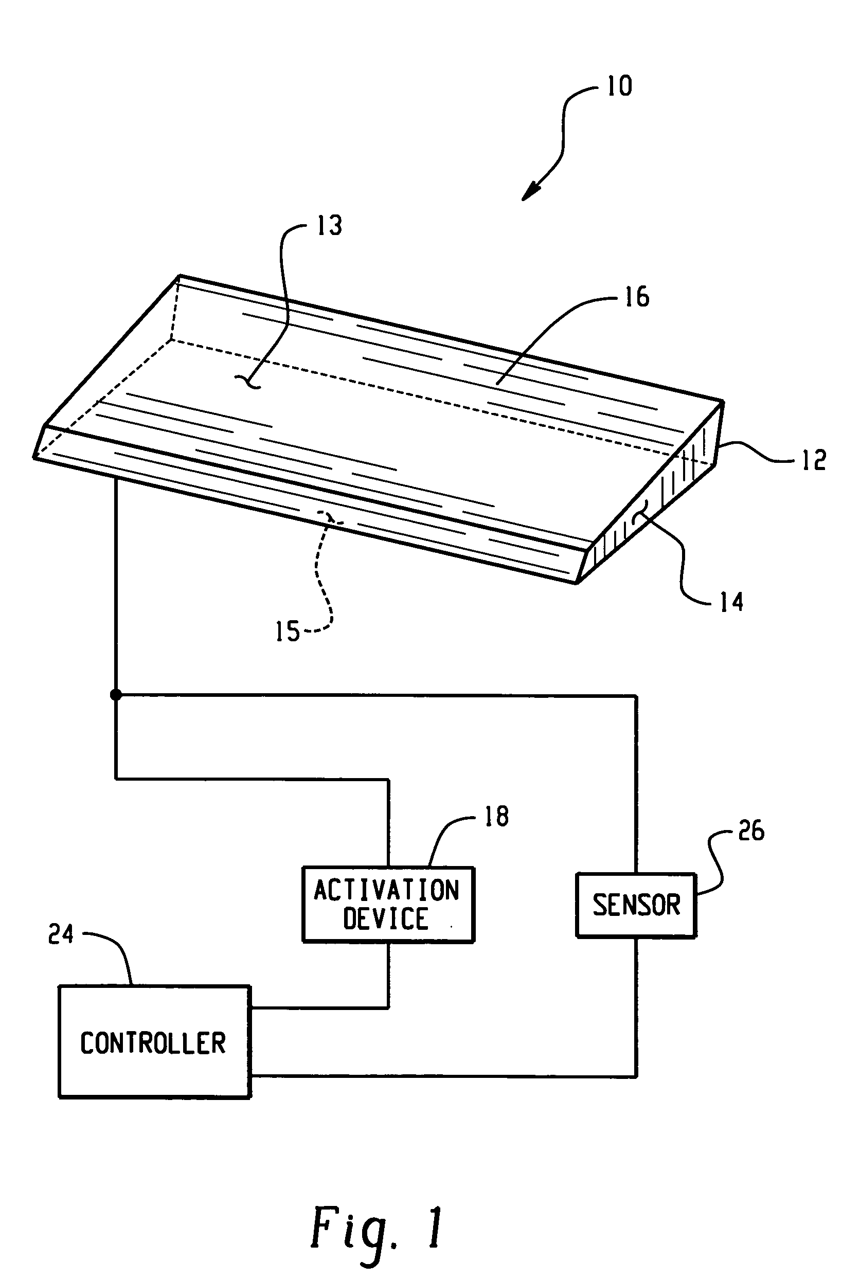
[0062] In this example, the airflow control device can be formed of an active material such as has been previously described in relation to FIG. 1. The airflow device is positioned in a cooperating relationship with the hood and / or the front grill, and / or the underside of the vehicle, and / or the forward portion of the vehicle side. In other words, the airflow device can be positioned anywhere on and / or in the vehicle that will provide a selectively controlled airflow across and through the radiator, fuel cell, fuel cell compartment, engine, and / or engine compartment.

[0063] By way of illustration, the airflow device in the form of louvers can be fabricated from a shape memory polymer. Resistive wires are embedded in the SMP louvers to provide selective resistive heating. The wiring is in operative communication with a control module for selectively introducing current to the wires such as, for example, when the coolant temperature exceeds a threshold value. The current flow would, t...

example 2

[0065] In this example, portions of the airflow control device are formed of the active material. As in Example 1, the airflow device is in the form of louvers and is positioned to provide controlled airflow or increased airflow across and / or through the radiator, fuel cell, fuel cell compartment, engine, and / or engine compartment. The louver can comprise thin strips of a shape memory alloy, for example, that are embedded at regular spaced intervals from top to bottom across a width of the louvers, such as is shown in FIG. 3. The shape memory alloy has a trained curvilinear shape at high temperatures, e.g., temperatures greater than the austenite transition temperature.

[0066] During operation when coolant air is desired, the SMA portions are heated through resistance heating so as to assume their high temperature trained curvilinear shape, which increases airflow through the louvers. The number and size of the SMA portions are chosen to cause deformation of the remaining (non-SMA) ...

example 3

[0068] In this example, louvers can be formed of any suitable material, including but not limited to, thermoplastics, metals, shape memory materials, and the like, and positioned as in Example 1. The louvers are connected to an externally controlled mechanism based on a shaped memory material similar to that shown in FIG. 4. For example, an upper edge of a louver is connected to a rod, which can rotate about its axis to change the relative position of the louver. A conventional spring and an SMA wire are attached to the rod in opposing fashion such that the tensions balance one another. As such, rotation of the rod will cause tension in the rod or the SMA wire depending on the rotation direction.

[0069] At low coolant temperatures, the tension in the spring in combination with the reduced stiffness and increased length (martensite phase) of the SMA maintains the louver in a closed position. Applying sufficient heat to exceed the austenite transition temperature causes stiffening and...


PUM


Abstract

An airflow control device comprises a body and an active material in operative communication with the body. The active material, such as a shape memory material, is operative to change at least one attribute in response to an activation signal. The active material can change its shape, dimensions and/or stiffness producing a change in at least one feature of the airflow control device such as shape, dimension, location, orientation, and/or stiffness to control vehicle airflow to better suit changes in driving conditions such as the need for increased airflow through the radiator due to increases in engine coolant temperature. As such, the device improves vehicle fuel economy while maintaining proper engine cooling. An activation device, controller and sensors may be employed to further control the change in at least one feature of the airflow control device such as shape, dimension, location, orientation, and/or stiffness of the device. A method for controlling vehicle airflow selectively introduces an activation signal to initiate a change of at least one feature of the device that can be reversed upon discontinuation of the activation signal.

Description

CROSS REFERENCE TO RELATED APPLICATIONS [0001] This application relates to and claims priority to U.S. patent Ser. No. 60 / 526,785, filed on Dec. 4, 2003, incorporated herein by reference in its entirety.BACKGROUND [0002] The present disclosure relates to devices for controlling vehicle airflow and, more particularly, to devices for controlling vehicle airflow which can be adjusted through changes in active materials in response to varying conditions, the adjustment being affected through shape, dimension and / or stiffness changes in the active material. [0003] Airflow over, under, around, and / or through a vehicle can affect many aspects of vehicle performance including vehicle drag, vehicle lift and down force, cooling / heat exchange for a vehicle powertrain, air conditioning systems, and brakes. Reductions in vehicle drag improve fuel economy. Vehicle lift and downforce can affect vehicle stability and handling. As used herein, the term “airflow” refers to the motion of air around an...

Claims


Application Information

Patent Timeline
Patent Type & Authority Applications(United States)
IPC IPC(8): B60H1/00B62D35/00B64C1/00B64C3/00B64C5/00B64C23/00E05F15/20F15D1/10
CPCB60H2001/00092B60K11/085B62D35/00Y02T50/34B64C2027/7288F15D1/10B64C23/00Y02T10/88Y02T50/30
Inventor AASE, JAN H.BROWNE, ALAN L.JOHNSON, NANCY L.ULICNY, JOHN C.
Owner GM GLOBAL TECH OPERATIONS LLC
Why Eureka
Try Eureka