Specialized hollow fiber membranes for in-vivo plasmapheresis and ultrafiltration

a technology of plasmapheresis and ultrafiltration, which is applied in the direction of membranes, filtration separation, separation processes, etc., can solve the problems of inconvenient placement of in-vivo plasmapheresis, poor elongation and breaking strength of conventional fiber membranes, and inability to meet the requirements of in-vivo placement for safety reasons, etc., to achieve biocompatibility of performance properties and materials, improve permeability rate, and increase the effect of permeability

Inactive Publication Date: 2005-06-09
TRANSVIVO
View PDF2 Cites 7 Cited by
  • Summary
  • Abstract
  • Description
  • Claims
  • Application Information

AI Technical Summary

Benefits of technology

[0005] The specialized hollow fiber membranes described herein are capable of separation of plasma and/or plasma components from blood and have the unique morphology, performance properties and materials biocompatible characteristics necessary for effective and optimal utilization for in-vivo vascular implantation as the operating element in devices as described in the aforesaid patents for the separation and extraction of plasma and plasma components from the blood. The hollow fiber membrane is tubular in shape and generally circular in cross-section, having a coaxial inner lumen along the length of the fiber in its center. The wall volume of the fibers is asymmetrical with a variable morphology from the outer diameter to that of the inner diameter, having a higher mass density and smaller mean pore diameter at the outer wall and a lower mass density and larger mean pore diameter at the inner wall. The preferred fibers described herein are characterized by having an average elongation breaking force strength of at least about 0.2 lbs. and preferably above about 0.3 lbs. and...

Problems solved by technology

Commercially available membranes, while acceptable in an encapsulated device external to the body in which the fibers are protected and not subjected to flow and pressure fluctuation, would not be acceptable for an in-vivo placement for safety reasons.
Such conventional fiber membran...

Method used


Image

  • Specialized hollow fiber membranes for in-vivo plasmapheresis and ultrafiltration
  • Specialized hollow fiber membranes for in-vivo plasmapheresis and ultrafiltration
  • Specialized hollow fiber membranes for in-vivo plasmapheresis and ultrafiltration

Examples


Embodiment Construction

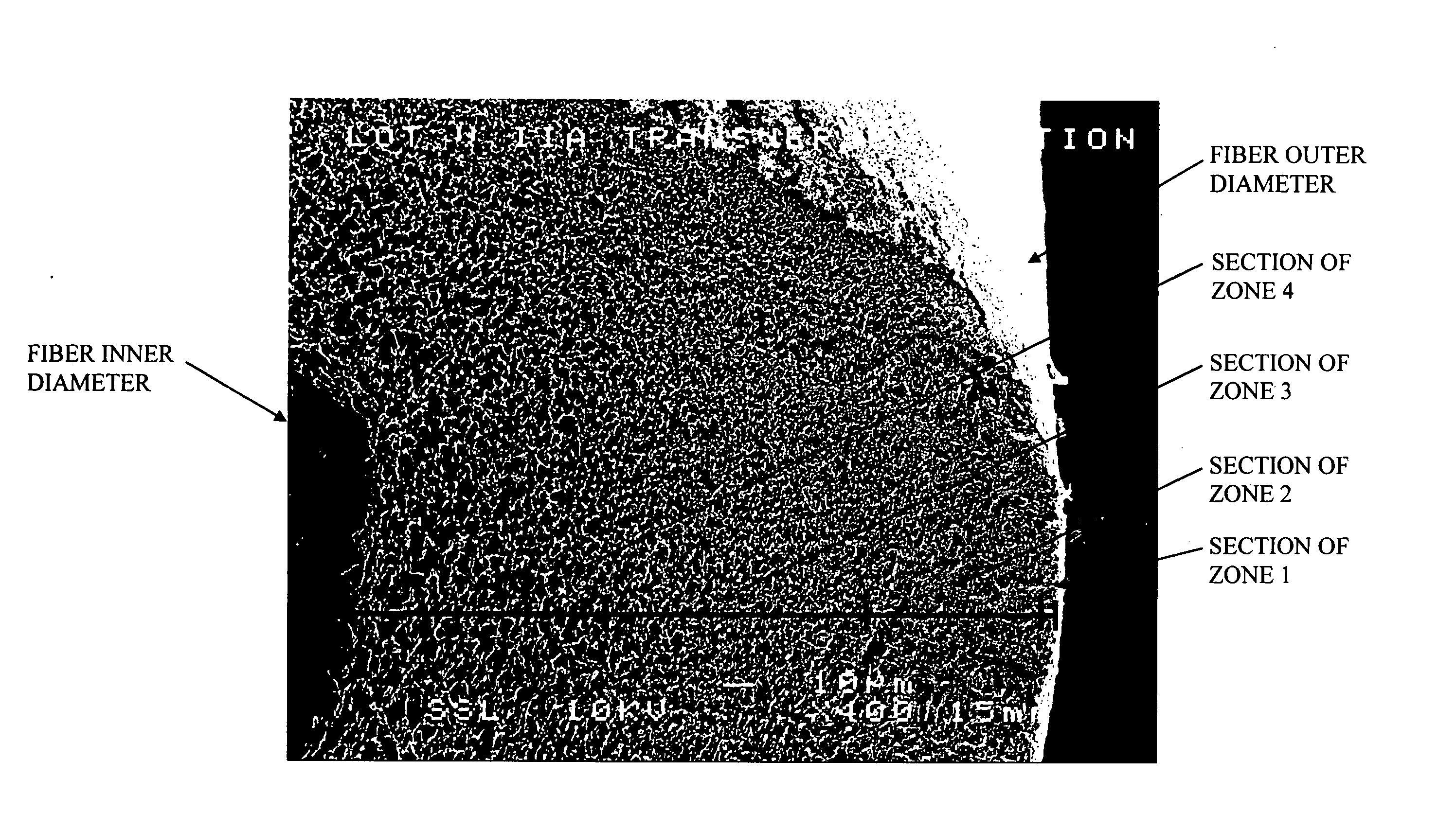
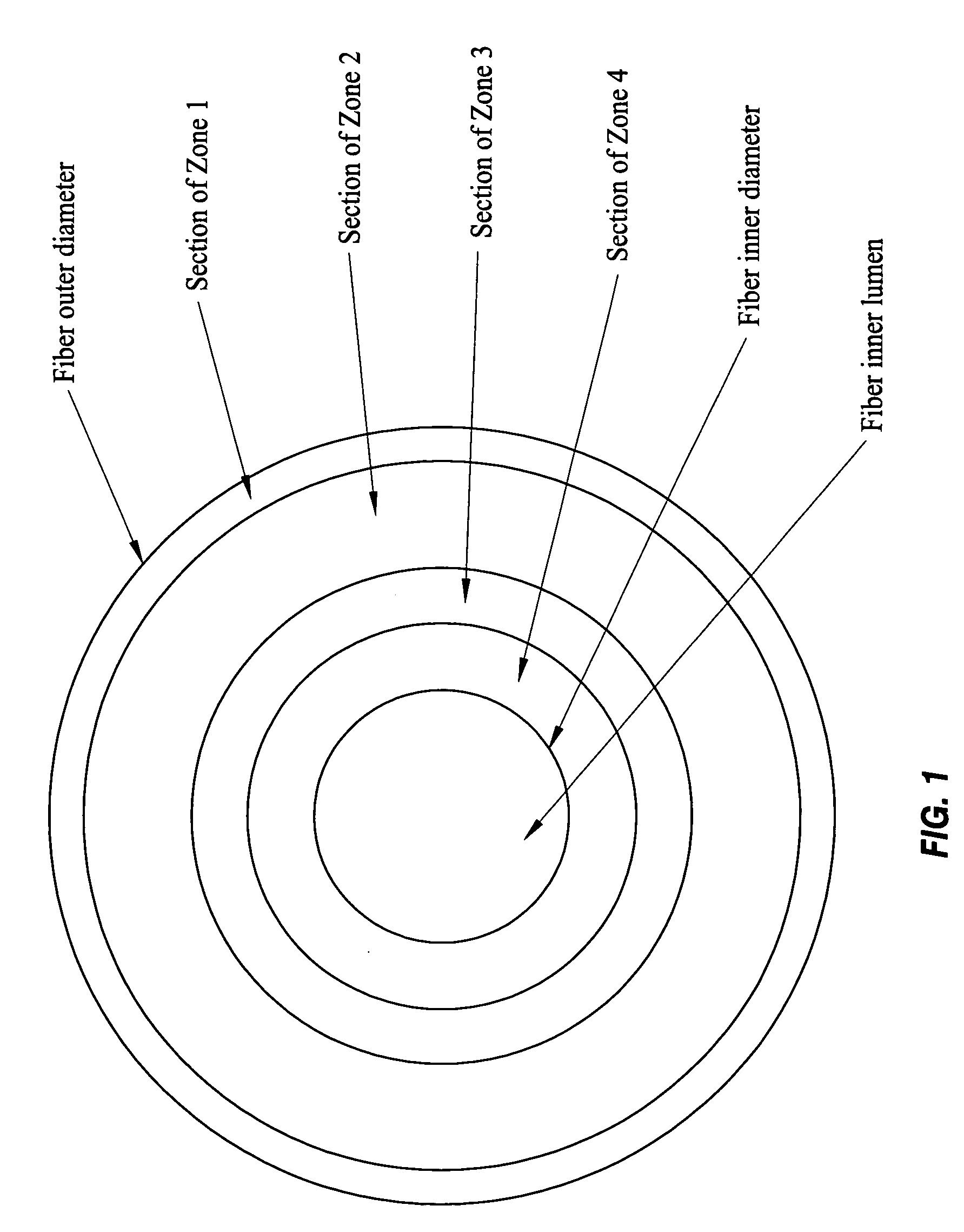
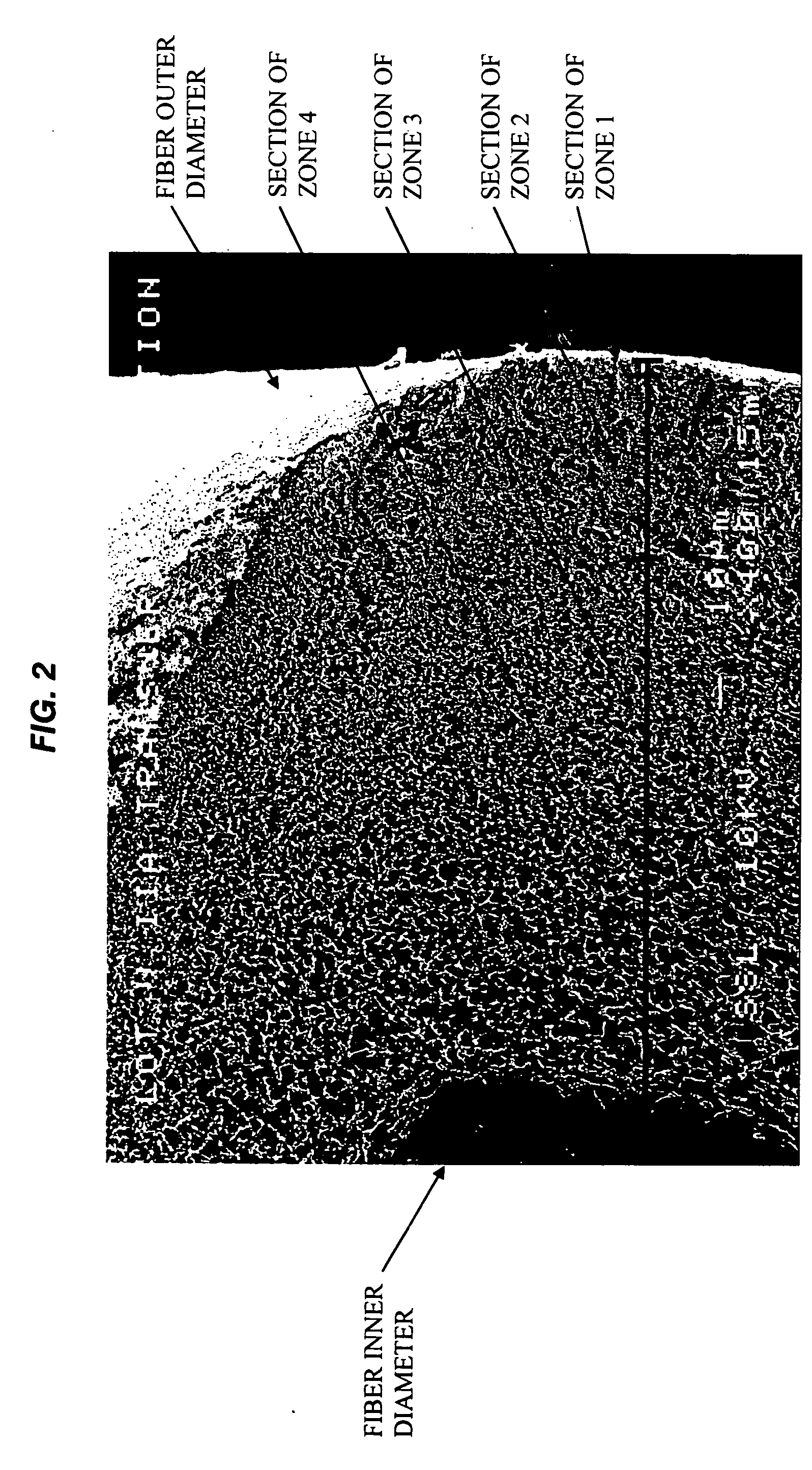
[0013] As illustrated in FIGS. 1-7, the features of the fiber wall of the membrane of the invention include a pore and void structure defined within frames or solid walls which form boundaries of the pores. The pores are voids of variable definitive sizes which permit passage of fluid through the fiber wall to the lumen and which pores obstruct the passage of components larger than the pore diameter. As illustrated particularly in FIG. 3, the pores are irregular-shaped voids bounded by solid frames to form irregular tortuous paths for irregular and regular-shaped solutes. The wall structure of the fiber from the outer surface to the lumen is a continuum with non-linear pore and void distribution. The resulting structure is a continuous change in mass density between the outer surface of the fiber and the inner lumen surface and whereby the pore size gradually changes between the fiber wall surfaces. The fiber wall illustrated is substantially without macrovoids. The fiber wall struc...


PUM

PropertyMeasurementUnit
Pore sizeaaaaaaaaaa
Pore sizeaaaaaaaaaa
Pore sizeaaaaaaaaaa

Abstract

An in-vivo plasmapheresis and/or in-vivo ultrafiltration membrane comprises elongated hollow fibers each fiber having an interior lumen extending along the fiber length, the fiber wall having a plurality of zones between the inner and outer wall surfaces, each of the zones having a mass density different than the mass density of an adjacent zone. The fiber wall is characterized by having a lower mass density zone at the inner wall surface and a higher mass density zone at the outer wall surface. The fiber is further characterized by having an average elongation breaking force strength of at least about 0.2 lbs. and an average elongation of at least about 45%.

Description

RELATED APPLICATIONS [0001] This application is a continuation-in-part of U.S. application Ser. No. 10 / 666,185, filed Sep. 27, 2003, which is incorporated herein by reference in its entirety, and which is a divisional of U.S. application Ser. No. 09 / 549,131, filed Apr. 13, 2000.BACKGROUND OF THE INVENTION [0002] In U.S. Pat. Nos. 4,950,224, 5,152,743, 5,151,082, 5,735,809, and 5,980,478 there are disclosed methods and apparatus for carrying out in-vivo plasmapheresis for separating plasma from other blood components within the body and blood vessels of the patient. The apparatus includes pumping means to create a trans-membrane pressure (TMP) and motivate the flow of fluid from within the in-vivo system, whereby blood plasma is pumped from the patient to a treatment means such as a dialyzer apparatus in which toxic metabolic waste in the plasma is removed. After the plasma is treated for removal of waste products, excess fluids, toxins, and / or other deleterious plasma proteins, the ...

Claims


Application Information

Patent Timeline
IPC IPC(8): A61M1/16A61M1/34B01D67/00B01D69/02B01D69/08B01D71/68
CPCA61M1/1678A61M1/34B01D67/0016B01D69/02B01D2325/022B01D69/08B01D69/12B01D71/68B01D69/04A61M1/3403
Inventor GORSUCH, REYNOLDS G.GRAGE, HENRYHANDLEY, HAROLD JR.PETERS, HAROLDKEARNS, JACOB C.
Owner TRANSVIVO
Why Eureka
Try Eureka