Twist lock assembly

a twist lock and assembly technology, applied in the direction of couplings, hose connections, combustion-air/fuel-air treatment, etc., can solve the problems of reducing the efficiency of the air induction and distribution system, and achieve the effects of improving the ability to prevent leakage of evaporative emissions, reducing turbulence, and improving the ability to prevent leakag

Inactive Publication Date: 2005-06-09
GM GLOBAL TECH OPERATIONS LLC
View PDF12 Cites 34 Cited by
  • Summary
  • Abstract
  • Description
  • Claims
  • Application Information

AI Technical Summary

Benefits of technology

[0005] The twist lock assembly in accordance with the present invention advantageously provides a greatly improved ability to prevent leakage of evaporative emissions through the joint, which provides an improved capability to meet PLEV and ZLEV emission requirements without the cost of a hydrocarbon absorber. The twist lock assembly reduces turbulence and improves the quality of the air flow path past the twist lock assembly by having the same diameter on both sides of the joint as there is no stepped surface therein and allows for shorter conduits since the flow path is not interrupted by the connection. In addition, the twist lock assembly automatically aligns the first and second flanges, eliminating the need to stretch the end of the duct over the mating part and then tightening as a separate operation.

Problems solved by technology

Any connection less than an airtight connection reduces the efficiency of the air induction and distribution system.

Method used


Image

  • Twist lock assembly
  • Twist lock assembly
  • Twist lock assembly

Examples


Embodiment Construction

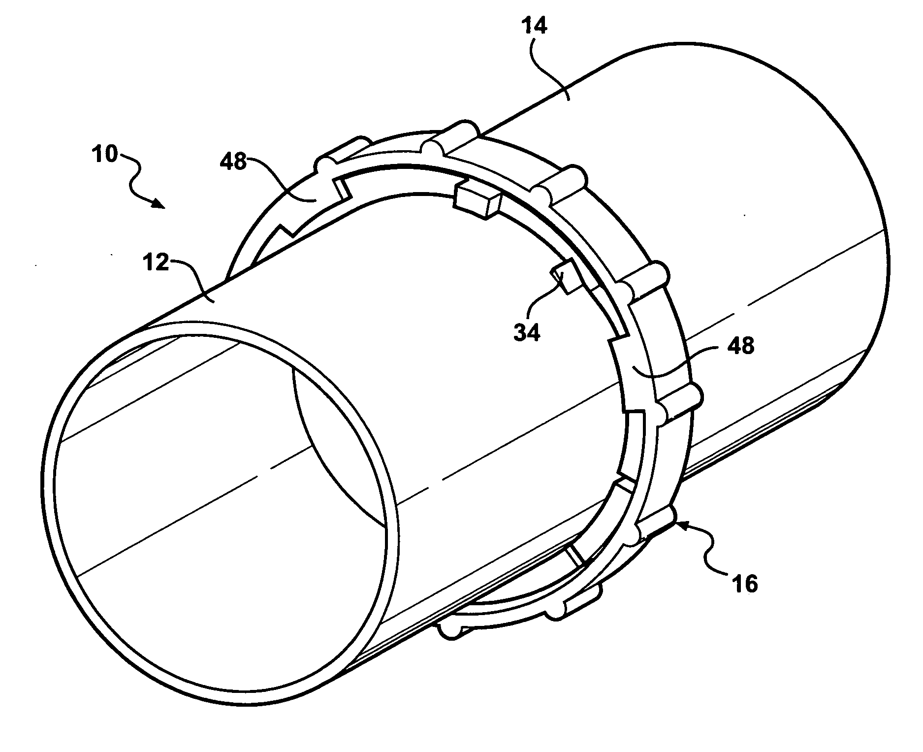
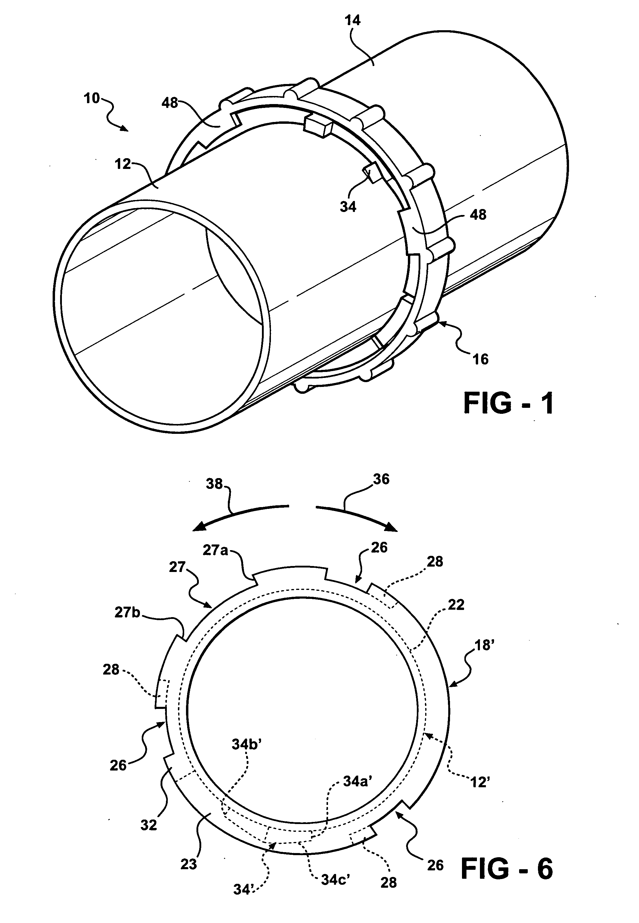
[0013] Referring now to FIG. 1, a twist lock assembly in accordance with the present invention is indicated generally at 10. The twist lock assembly 10 includes a first conduit 12 and a second conduit 14 having a locking ring 16 rotatably mounted thereon for assisting in the engagement of the first conduit 12 and the second conduit 14, discussed in more detail below.

[0014] Preferably the first conduit 12 is adapted to be attached to an air receiving engine component 9, best seen in FIG. 2, including, but not limited to, an air cleaner, a resonator, and a throttle body. The first conduit 12 is an air receiving conduit and the second conduit 14 is an air supplying conduit adapted to conduct the air from a source such as an air intake. Alternatively, the first 12 and second 14 conduits are any type of plumbing conduits wherein an airtight seal, discussed in more detail below, is desired for transferring fluid therebetween including, but not limited to, air filters, ducts, mass air flo...


PUM


Abstract

A twist lock assembly includes an annular first flange at an open end of a first conduit attached to a fluid receiving component. The first flange has an alignment slot and at least one locking slot formed therein. A fluid conducting conduit has an annular second flange at an open end thereof. The second flange includes an alignment tab formed thereon. A locking ring rotatably mounts on the second flange and includes at least one locking tab formed thereon. When the first flange is attached to the component, the alignment tab engages the alignment slot and the at least one locking tab is aligned with the at least one locking slot. Rotating the locking ring relative to the second flange draws the first and second flanges into airtight engagement and locks the conduit to the component.

Description

BACKGROUND OF THE INVENTION [0001] The present invention relates in general to air induction and distribution systems and, in particular, to a twist lock assembly for an air induction and distribution system. [0002] Air induction and distribution systems, such as those for automotive internal combustion engines, are well known. A typical automotive internal combustion engine air induction system includes a plurality of connections between various components of the system including, but not limited to, an air cleaner assembly, a resonator, and a throttle body. The types of connections utilized typically require the use of hand tools to assemble in order to provide an airtight connection at the joints. Any connection less than an airtight connection reduces the efficiency of the air induction and distribution system. [0003] It would be desirable to provide a means for sealing the joints on connections in an air induction and distribution system and the like that can seal the joints in...

Claims


Application Information

Patent Timeline
Patent Type & Authority Applications(United States)
IPC IPC(8): F16L21/00F16L37/252
CPCF02M35/10144F16L37/113
Inventor BENSCOTER, SCOTT J.SKELTON, MICHAEL E.PARKER, ROCKO D.
Owner GM GLOBAL TECH OPERATIONS LLC
Why Eureka
Try Eureka