Vehicle braking system

a technology for braking systems and vehicles, applied in braking systems, rotary clutches, fluid couplings, etc., can solve the problem that the conventional vehicle braking system does not allow a large hysteresis width, and achieve the effect of eliminating the feeling of idle strok

Active Publication Date: 2005-06-09
AUTOLIV NISSIN BRAKE SYST JAPAN CO LTD
View PDF10 Cites 14 Cited by
  • Summary
  • Abstract
  • Description
  • Claims
  • Application Information

AI Technical Summary

Benefits of technology

[0014] With the configuration of the fifth aspect, since the elastic body is preloaded by the spring member, even if the elastic body loses elasticity, the loss of elasticity is absorbed by the spring member, and thus it is possible to eliminate a feel of an idle stroke during a normal braking operation and obtain two-step operating simulation characteristics using the elastic body and spring member irrespective of the loss of elasticity of the elastic body.

Problems solved by technology

However, the conventional vehicle braking system does not allow large hysteresis width.

Method used


Image

  • Vehicle braking system
  • Vehicle braking system
  • Vehicle braking system

Examples


first embodiment

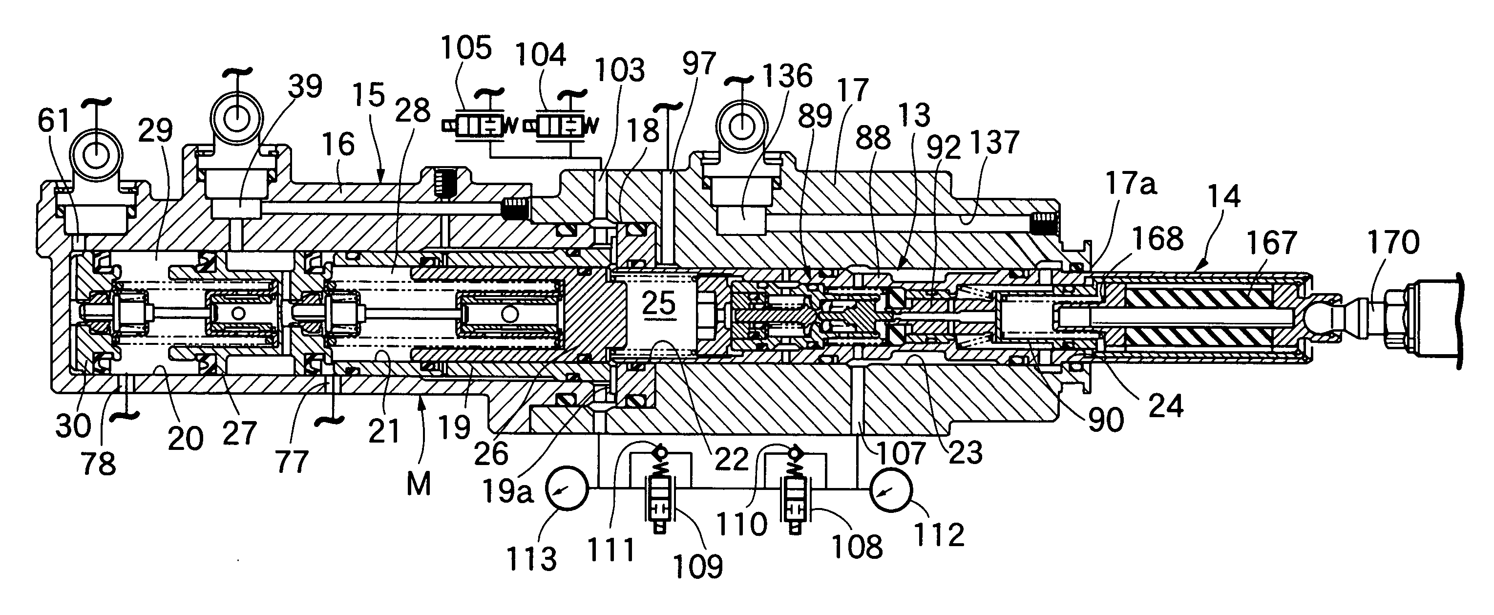
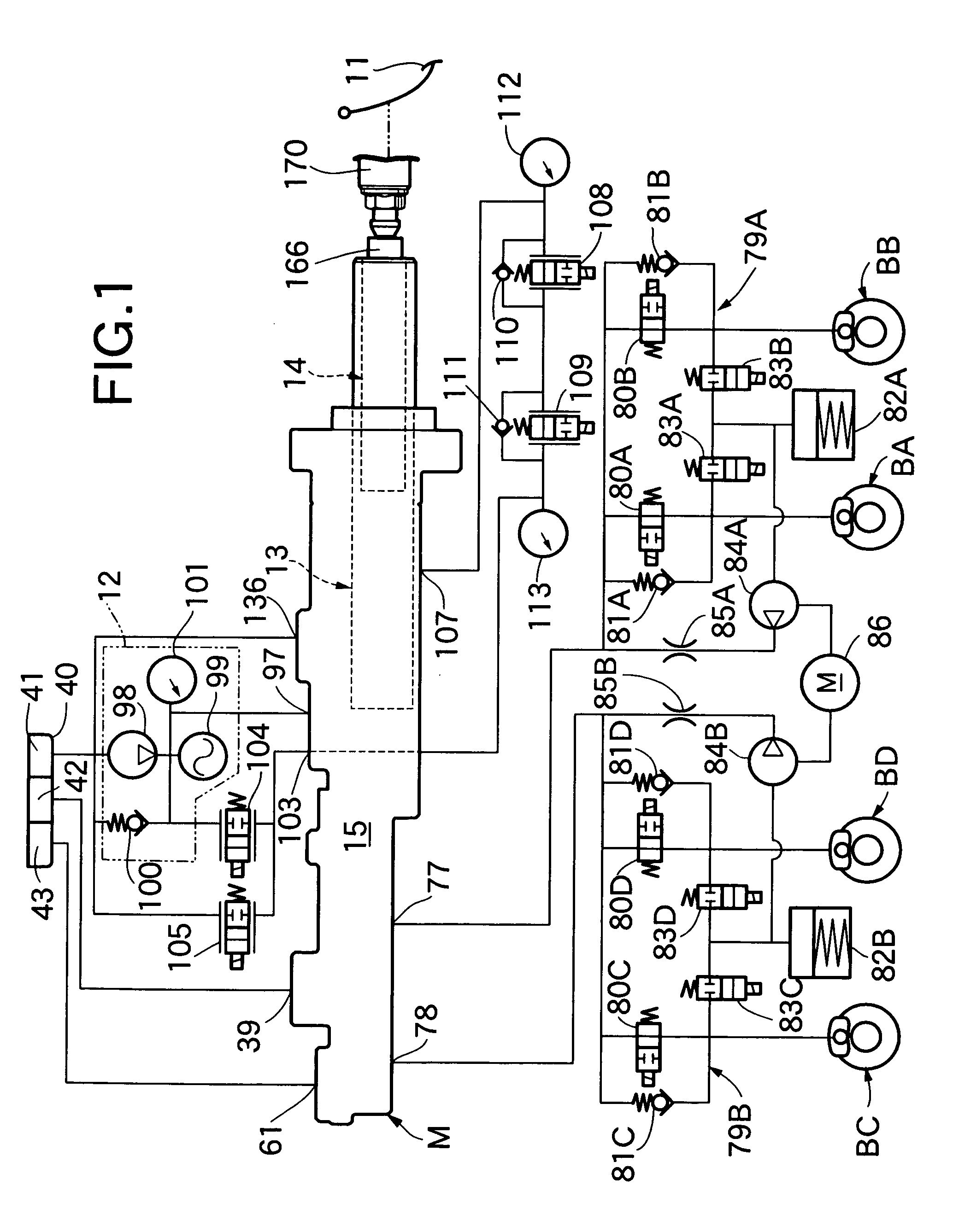
[0025] the present invention will be described with reference to FIGS. 1 to 8. Referring first to FIG. 1, a braking system for a four-wheeled vehicle comprises: a tandem master cylinder M; a hydraulic booster 13 which regulates hydraulic pressure of a hydraulic power source 12 according to a brake operating force inputted from a brake pedal 11 serving as a brake operating member, and which applies the hydraulic pressure to the master cylinder M; and a brake stroke simulator 14 interposed between the brake pedal 11 and hydraulic booster 13.

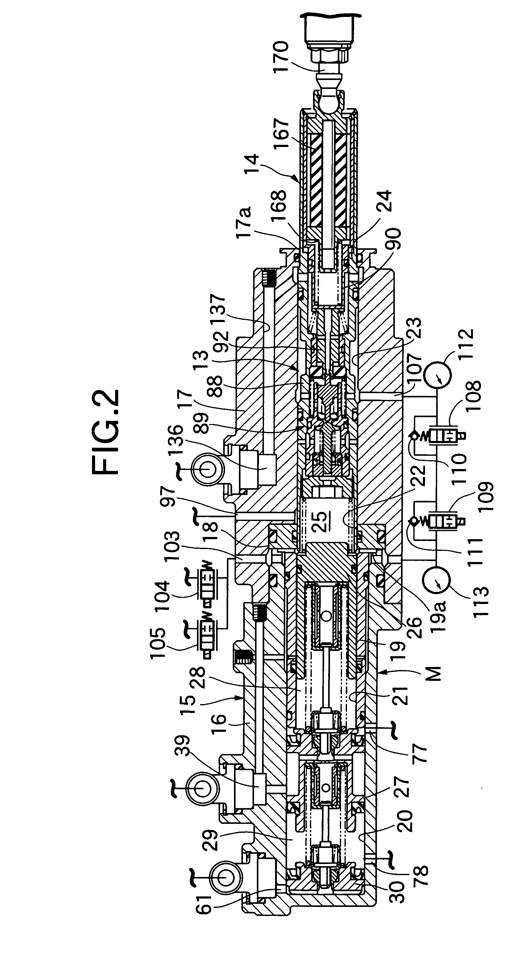
[0026] Referring also to FIG. 2, a casing 15 common to the master cylinder M and hydraulic booster 13 houses a first cylinder body 16 of a bottomed cylindrical shape with its front end closed; a second cylinder body 17 which is cylindrical in shape, has an inward flange 17a on its rear end, and is coupled coaxially with the rear part of the first cylinder body 16; a ring-shaped separator 18 sandwiched between the first and second cylinder bodies 16...

second embodiment

[0128]FIG. 9 shows the present invention, where a brake stroke simulator 14′ comprises an input piston 166 axially slidably housed in a control piston 90, as well as an elastic body 167′ and the coil spring 168 interposed in series between the input piston 166 and control piston 90. The brake stroke simulator 14′ is housed in the control piston 90 and opens the control piston 90 to the atmosphere.

[0129] The elastic body 167′ is made of elastic material such as rubber and has a cylindrical shape. The elastic body 167′ and the metallic coil spring 168 smaller in spring load than the elastic body 167′ are interposed in series between the input piston 166 and control piston 90 via an intermediate transmitting member 171.

[0130] The elastic body 167′ is formed into a cylindrical shape with its outer circumference tapered in the axial direction such that one end is larger in diameter than the other. The elastic body 167′ comes into resilient contact with the inner circumference of the con...


PUM


Abstract

A vehicle braking system includes: a hydraulic booster which applies output hydraulic pressure of a hydraulic power source to a boosted hydraulic pressure chamber after regulating the output hydraulic pressure as a control piston operates to balance reaction force generated by hydraulic pressure of the boosted hydraulic pressure chamber with brake operating input; and a brake stroke simulator installed between the brake operating member and the control piston in order for a driver to feel operating strokes of the brake operating member. The brake stroke simulator has: an input member axially slidably housed in the control piston of a cylindrical shape and linked to the brake operating member; and an elastic body interposed between the input member and the control piston. The elastic body is formed into a tubular shape so as to come into resilient contact with an inner circumference of the control piston by expanding its diameter under the action of axial compressive force generated by forward movement of the input member. Consequently, the brake stroke simulator allows large hysteresis width in relationship between brake operating stroke and operating load.

Description

RELATED APPLICATION DATA [0001] The Japanese priority application Nos. 2003-406883 and 2003-406885 upon which the present application is based are hereby incorporated in their entirety herein by reference. BACKGROUND OF THE INVENTION [0002] 1. Field of the Invention [0003] The present invention relates to a vehicle braking system comprising: a hydraulic booster which has a control piston for achieving a balance between reaction force generated by hydraulic pressure of a boosted hydraulic pressure chamber capable of generating boosted hydraulic pressure to be applied to wheel brakes and brake operating input from a brake operating member, and which applies output hydraulic pressure of a hydraulic power source to the boosted hydraulic pressure chamber after regulating the output hydraulic pressure as the control piston moves axially; and a brake stroke simulator installed between the break operating member and the control piston in order for a driver to feel operating strokes of the b...

Claims


Application Information

Patent Timeline
Patent Type & Authority Applications(United States)
IPC IPC(8): B60T8/40B60T11/16B60T13/14
CPCB60T8/4077B60T11/16B60T13/147B60T13/145B60T13/142
Inventor MATSUNO, ISAOTAGATA, KAZUHIRO
Owner AUTOLIV NISSIN BRAKE SYST JAPAN CO LTD
Why Eureka
Try Eureka