Power sharing high frequency motor drive modular system

a high-frequency motor and modular system technology, applied in the direction of motor/generator/converter stopper, electronic commutator, dynamo-electric converter control, etc., can solve the problems of high cost of conventional bldc motor drivers using igbt switching elements, limited upper speed capability of conventional bldc motor drivers, and inability to meet the needs of a wide range of applications, so as to achieve low cost

Inactive Publication Date: 2005-06-09
THE BOEING CO
View PDF13 Cites 15 Cited by
  • Summary
  • Abstract
  • Description
  • Claims
  • Application Information

AI Technical Summary

Benefits of technology

[0010] The multiple groupings of half-bridge assemblies are typically connected to corresponding multiple “IN_HAND” windings for each phase. The “IN_HAND” windings are generally made up of two or more approximately identical coils wrapped around the same phase winding core. As a result, the common electromagnetic field around the “IN_HAND” windings has the effect of forcing approximately equal current sharing between the switching elements of the corresponding half-bridge assemblies.
[0011] A particular benefit of the disclosed exemplary embodiments of a BLDC motor control system is that both frequency and power scaling can be achieved with standard low cost switching elements, such as insulated gate bipolar transistors (IGBT's). This benefit is due to the exemplary frequency and power sharing circuit configurations of the half-bridge assemblies described herein.

Problems solved by technology

The upper speed capability of a conventional BLDC motor driver is typically limited to the switching speed of the IGBT elements in the half-bridge circuits used to drive the stator windings.
As such, conventional BLDC motor drivers using IGBT switching elements are generally limited to relatively low frequency (about 20 kHz maximum) and low power (about one horsepower maximum) applications.
While other switching devices with higher frequency capabilities are available, their cost is typically many times higher than the cost of a standard IGBT, which makes the costly high frequency devices generally undesirable for production applications.

Method used


Image

  • Power sharing high frequency motor drive modular system
  • Power sharing high frequency motor drive modular system
  • Power sharing high frequency motor drive modular system

Examples


Embodiment Construction

[0025] The following detailed description is merely exemplary in nature and is not intended to limit the invention or the application and uses of the invention. Furthermore, there is no intention to be bound by any expressed or implied theory presented in the preceding technical field, background, brief summary or the following detailed description.

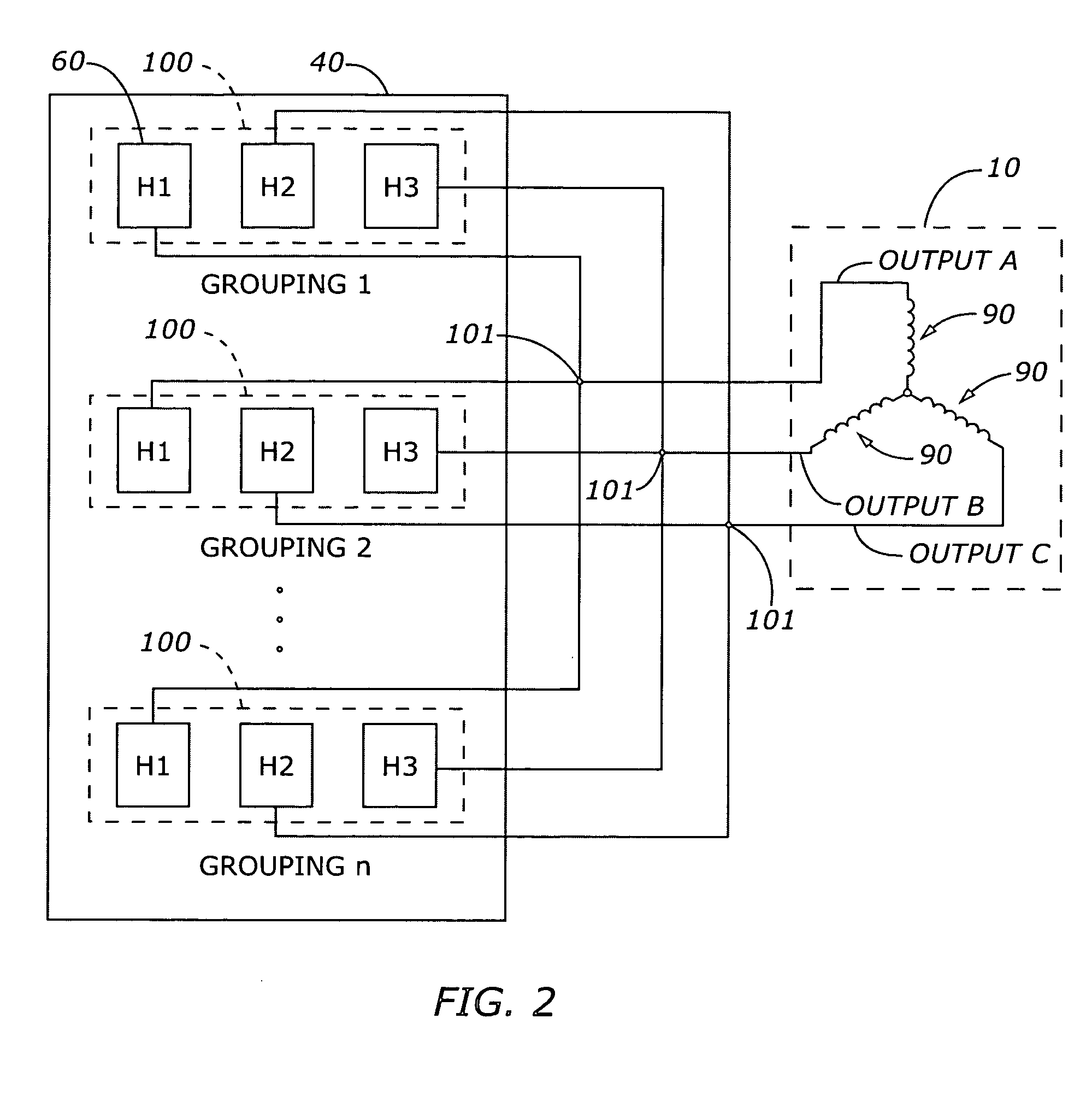
[0026] Various embodiments of the present invention pertain to the area of scaling the frequency and power capabilities of controller / drivers for BLDC motors. Combining multiple configurations of half-bridge assembly groupings in the controller / drivers enables the composite output frequency and power levels of the controller / drivers to exceed the limitations of the individual components used in the driver half-bridge assemblies. As such, the frequency and power scalability of the controller / drivers can be achieved with standard low-cost components.

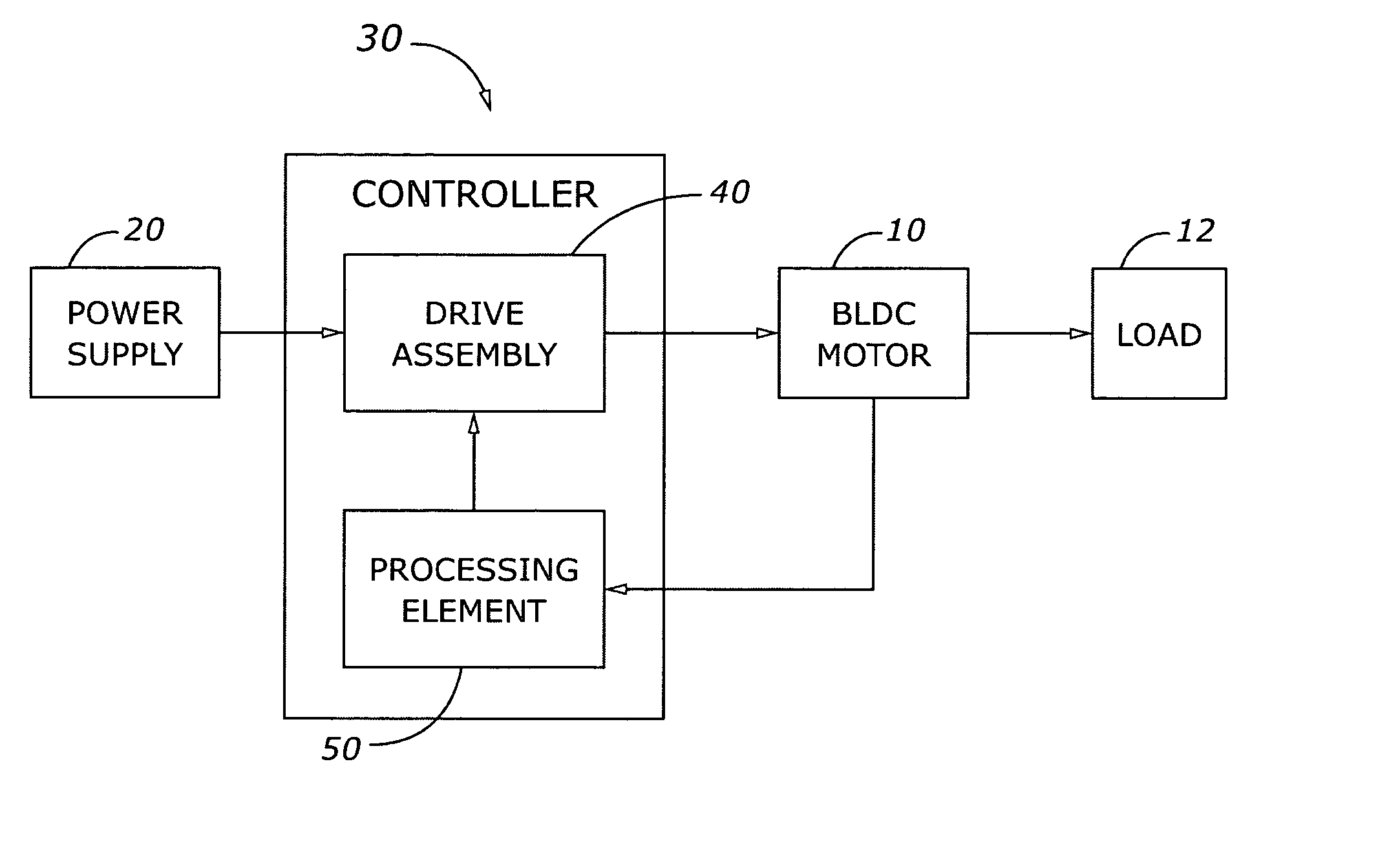
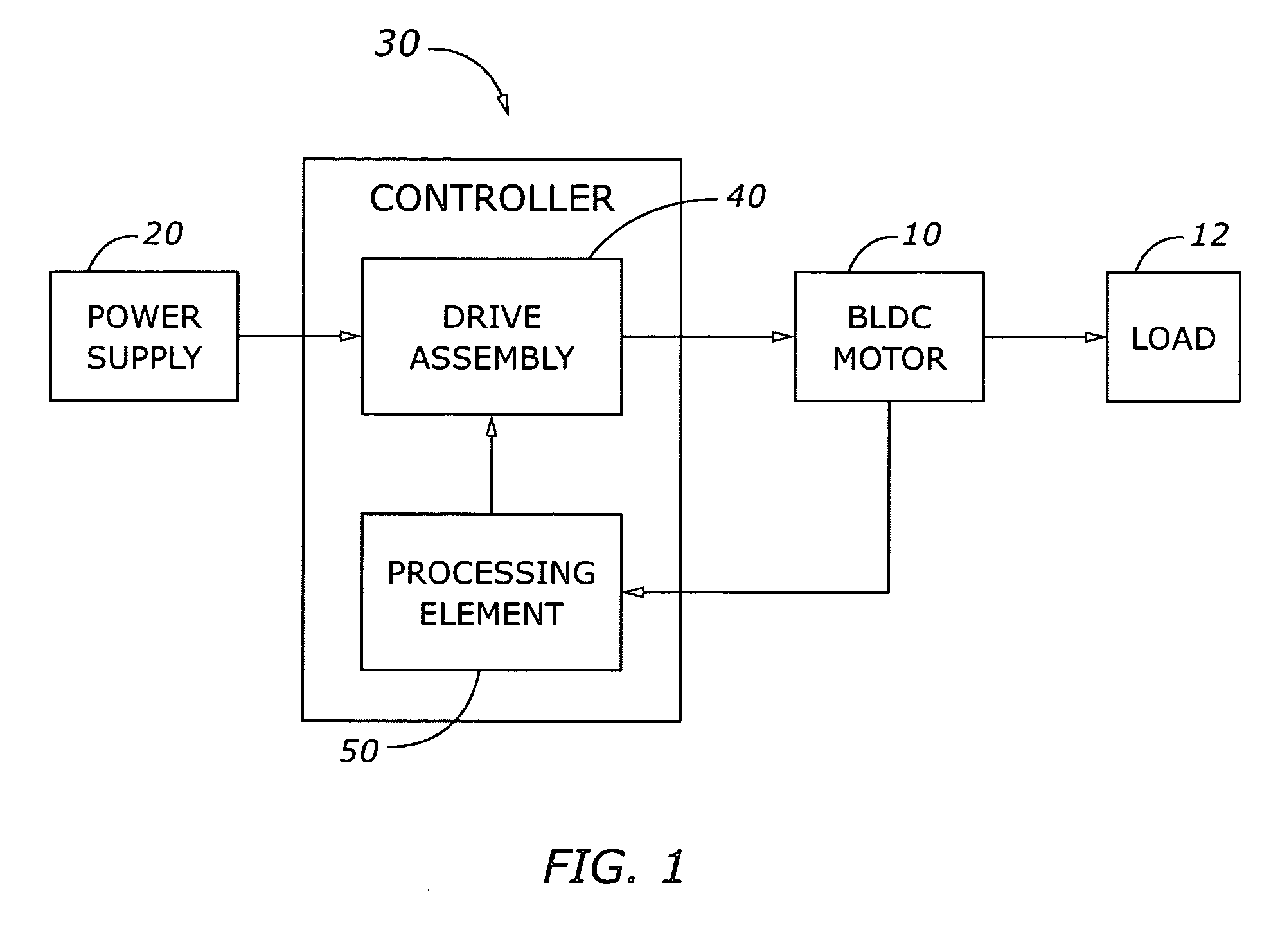
[0027] According to an exemplary embodiment of a system for controlling a BLDC motor 10 co...


PUM


Abstract

Methods and apparatus are provided for frequency and power scaling a drive assembly for a brushless direct current (BLDC) motor. The apparatus comprises multiple groups of half-bridge switching element assemblies connected to respective “In-Hand” phase windings of the BLDC. Each group of half-bridge assemblies receives time sliced commands from a processor so that the resultant frequency of the output drive signal can be higher than the frequency capability of an individual switching element. By effectively paralleling groups of half-bridge assemblies connected to respective In-Hand phase windings, the current delivered to the phase windings can be greater than the individual current capability of the switching elements in the half-bridge assemblies. The electromagnetic field generated in the “In-Hand” phase windings forces essentially equal current sharing in the respective driver switching elements. The disclosed techniques enable frequency and power scaling of motor drive assemblies using standard low-cost components.

Description

TECHNICAL FIELD [0001] The present invention generally relates to methods and devices for controlling an electric motor, and more particularly relates to a controller and associated drive assembly for controlling a brushless direct current (BLDC) motor. BACKGROUND [0002] Electric motors are used in many application areas, such as utilities, manufacturing, military, medicine, transport, and so forth. One type of electric motor in general use is known as a brushless direct current (BLDC) motor. In a BLDC motor, the stationary outside portion (stator) is typically composed of electromagnetic windings corresponding to the electrical phase configuration of the motor, and the rotating inner portion (rotor) is typically composed of two or more permanent magnets of opposite magnetic polarity. The stator windings are generally electrically connected to a controller / driver unit, where the controller typically provides commands to the driver to generate poly-phase input currents in the stator ...

Claims


Application Information

Patent Timeline
Patent Type & Authority Applications(United States)
IPC IPC(8): H02K23/00
CPCH02P6/10H02P6/001H02P6/34
Inventor ATMUR, ROBERT J.
Owner THE BOEING CO
Why Eureka
Try Eureka