Emergency stop circuit

Active Publication Date: 2005-06-09
FANUC LTD
View PDF11 Cites 8 Cited by
  • Summary
  • Abstract
  • Description
  • Claims
  • Application Information

AI Technical Summary

Benefits of technology

[0025] The emergency stop circuit of the present invention does not require a safety relay circuit composed of expensive safety relays with contact operation assurance. Further, an emergency stop is performed by outputting emergency stop commands doubly by the hardware and the software, whereby the emergency stop

Problems solved by technology

The conventional emergency stop circuit uses a safety relay circuit composed of safety relays in which operations of the contacts are assured, whereby specially-designed, expens

Method used


Image

  • Emergency stop circuit
  • Emergency stop circuit
  • Emergency stop circuit

Examples


first embodiment

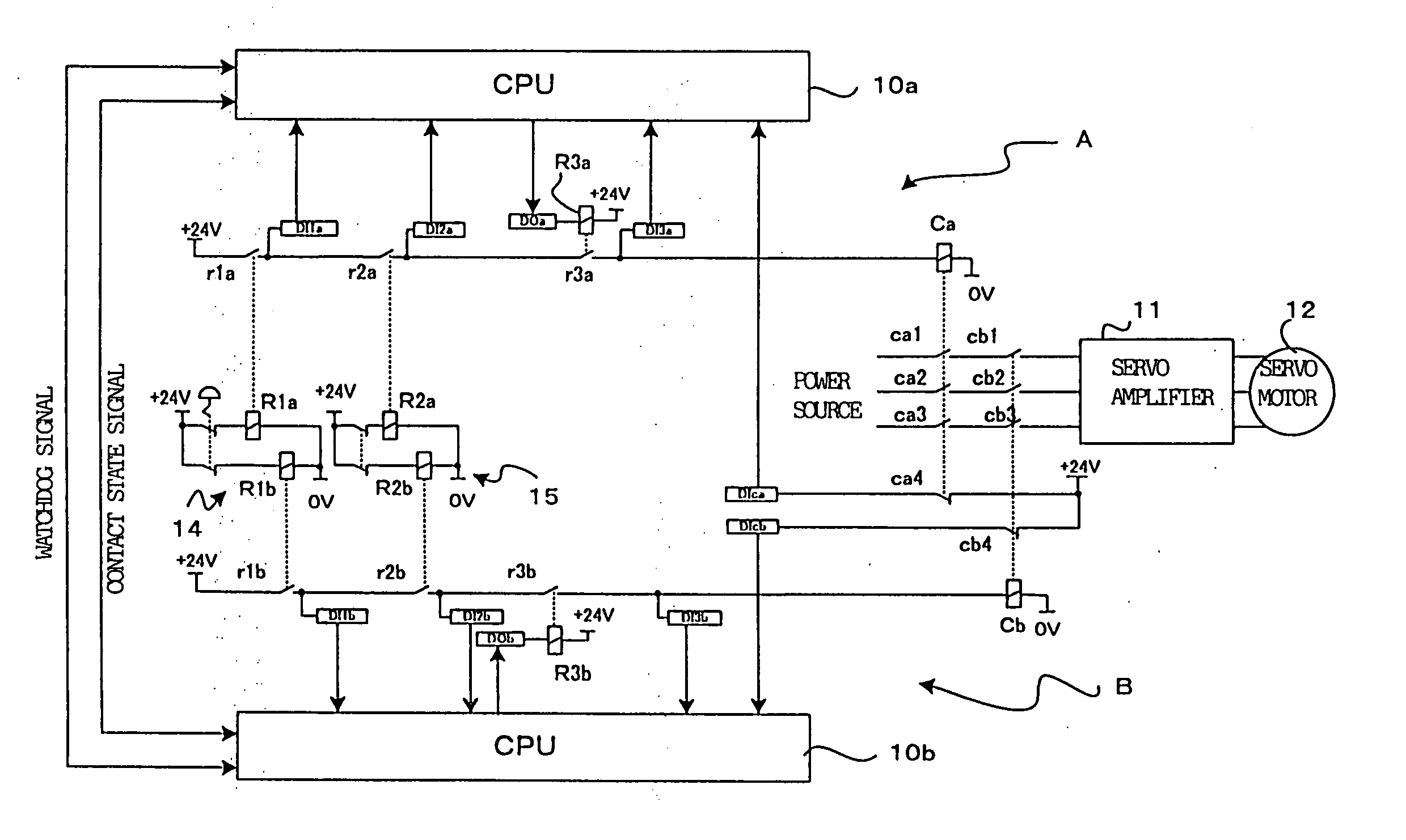
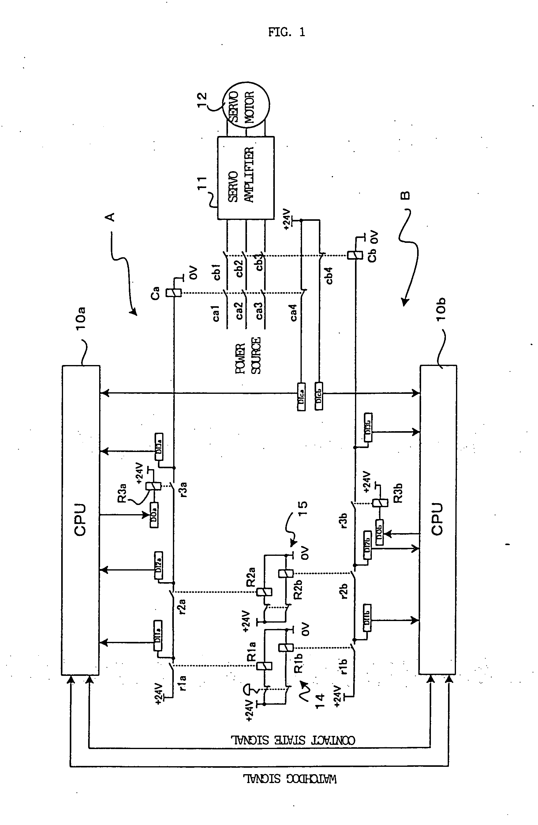
[0034]FIG. 1 is a circuit diagram of an emergency stop circuit according to the present invention, the circuit being applied to a driving motor in a robot, a machine tool or various industrial machinery.

[0035] Comparing with the conventional emergency stop circuit shown in FIG. 7, the present embodiment is characterized in that the safety relay circuit 13 is Omitted while another CPU is added so as to have two CPUs (a first CPU 10a and a second CPU 10b).

[0036] In the emergency stop circuit of FIG. 1, emergency stop factors are detected by independent two systems of circuits, as same as the emergency stop circuit of FIG. 7. The circuit has relays, and contacts to stop power supply to the relays, for the two systems of the emergency stop lines A and B, respectively. The emergency stop factors and the number thereof are different depending on machines to apply. In the example shown in FIG. 1, two emergency stop factors 14 and 15 are indicated. In this example, power supply to relays R...

second embodiment

[0070] Although, in the second embodiment, the digital output elements DO2a and DO2b and the relays R4a and R4b are provided, it may be acceptable that these digital output elements and the relays are not to be provided, and the third CPU 10c transmits an emergency stop command to the first CPU 10a and to the second CPU 10b as shown by the dashed lines in FIG. 6, and the first and second CPUs 10a and 10b, when received the emergency stop command, cause the contacts r3a and r3b of the relays R3a and R3b in their systems to be opened. Further, although, in FIG. 6, a watchdog signal WDS is also transmitted and received between the first CPU 10a and the second CPU 10b, abnormal operations in the first CPU 10a and the second CPU 10b can be detected due to the transmission and reception of the watchdog signals WDS performed between the first CPU 10a and the third CPU 10c and between the second CPU 10b and the third CPU 10c. Therefore, a detection of abnormality through the transmission an...


PUM


Abstract

Two emergency stop lines are provided. Due to contacts being opened by commands from emergency stop factors and from first and second CPUs, conducting to first and second contactors are stopped. Contacts of the contactors are opened, and power supply to the motor is interrupted, whereby an emergency stop is performed. Further, the first CPU on the first line transmits an abnormality signal to the second CPU when the states of the contacts on the self emergency stop line, detected by digital inputs, are abnormal, and the second CPU opens a contact on the self emergency stop line so as to cause the contactor to be non-excited to thereby stop power supply to the motor.

Description

BACKGROUND OF THE INVENTION [0001] 1. Field of the Invention [0002] The present invention relates to emergency stop circuits, in various machines such as robots or machine tools, for stopping operations thereof in an emergency. [0003] 2. Description of the Related Art [0004] In a robot system, a safety measure is taken by surrounding the robot operating range with a fence so as not to let a person come into the robot operating area within the fence. The fence is provided with a door or the like, and when the door is opened, an emergency stop signal is output so as to stop the operation of the robot. Further, when an operation is taught to the robot, a teaching pendant is controlled to operate the robot, so the teaching pendant is provided with an emergency stop command button or the like, whereby the operation of the robot is stopped in an emergency by inputting an emergency stop signal through the button (see, for example, Japanese Patent Application Laid-open No. 10-217180). [0005...

Claims


Application Information

Patent Timeline
IPC IPC(8): B25J19/06F16P3/16G05B19/18H01H47/00
CPCH01H47/004
Inventor HASHIMOTO, YOSHIKICHINO, NOBUOTANABE, YOSHIKIYOYUYAMA, MAKINE
Owner FANUC LTD
Why Eureka
Try Eureka