

Reference cell configuration for a 1T/1C ferroelectric memory
a ferroelectric memory and reference cell technology, applied in the field of ferroelectric memories, can solve the problems of reducing the operating margin of the single bit line of opposite polarity, the noise generated by capacitive coupling between bit lines, and the cumulative noise of the bit lines within the array
- Summary
- Abstract
- Description
- Claims
- Application Information
AI Technical Summary
Benefits of technology
Problems solved by technology
Method used
Image

Examples
Embodiment Construction
[0079] A memory cell 28 according to the present invention is shown in FIG. 14. Memory cell 28 is a combination of two 1T / 1C ferroelectric memory cells, physically laid out approximately as shown in FIG. 14. Memory cell 28 includes a first 1T / 1C memory cell coupled to a common parallel plate and word lines, designated CPL and WLE, respectively. The first 1T / 1C cell is also coupled to an orthogonal bit line designated BL. A second 1T / 1C memory cell is also coupled to a common parallel plate and word lines, designated CPL and WLO, respectively. The second 1T / 1C cell is also coupled to an orthogonal bit line designated BLb. Alternatively, the common plate line can be separated into individual plate lines PLO and PLE as shown in FIG. 14.
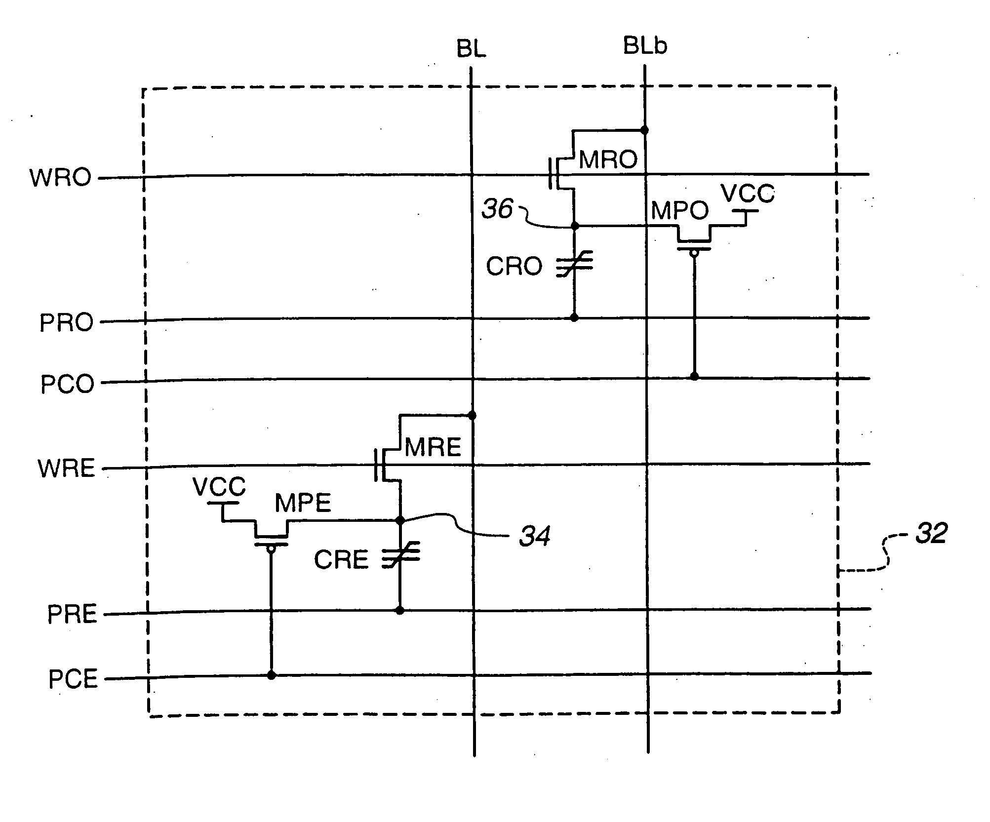
[0080] A reference cell 32 for use with memory cell 28 is shown in FIG. 15. The reference memory cells 32 are utilized in a folded bit line architecture array shown in FIG. 18 and described in further detail below. Reference cell 32 is a combination of ...
PUM
 Abstract
Description
Claims
Application Information