
Fastener

Inactive Publication Date: 2005-06-09
ZEN KENCHIKU SEKKEI JIMUSHO TOKIOTOKYO
View PDF9 Cites 61 Cited by
  • Summary
  • Abstract
  • Description
  • Claims
  • Application Information

AI Technical Summary

Benefits of technology

[0003] In order to attain the above object, the present invention provides particularly a fastener structure which allows engagement / coupling by a single push or strike action, and further not only provides high impact and vibration resistances, but also possibility of very easy removal by substantially a single push or strike action when it is removed again after making engagement / coupling once.

Problems solved by technology

However, many are accompanied by difficulty when being removed by releasing their engagement / coupling, even though their engagement / coupling is possible by, for example, a single push or strike action.

Method used


Image

  • Fastener
  • Fastener
  • Fastener

Examples


second embodiment

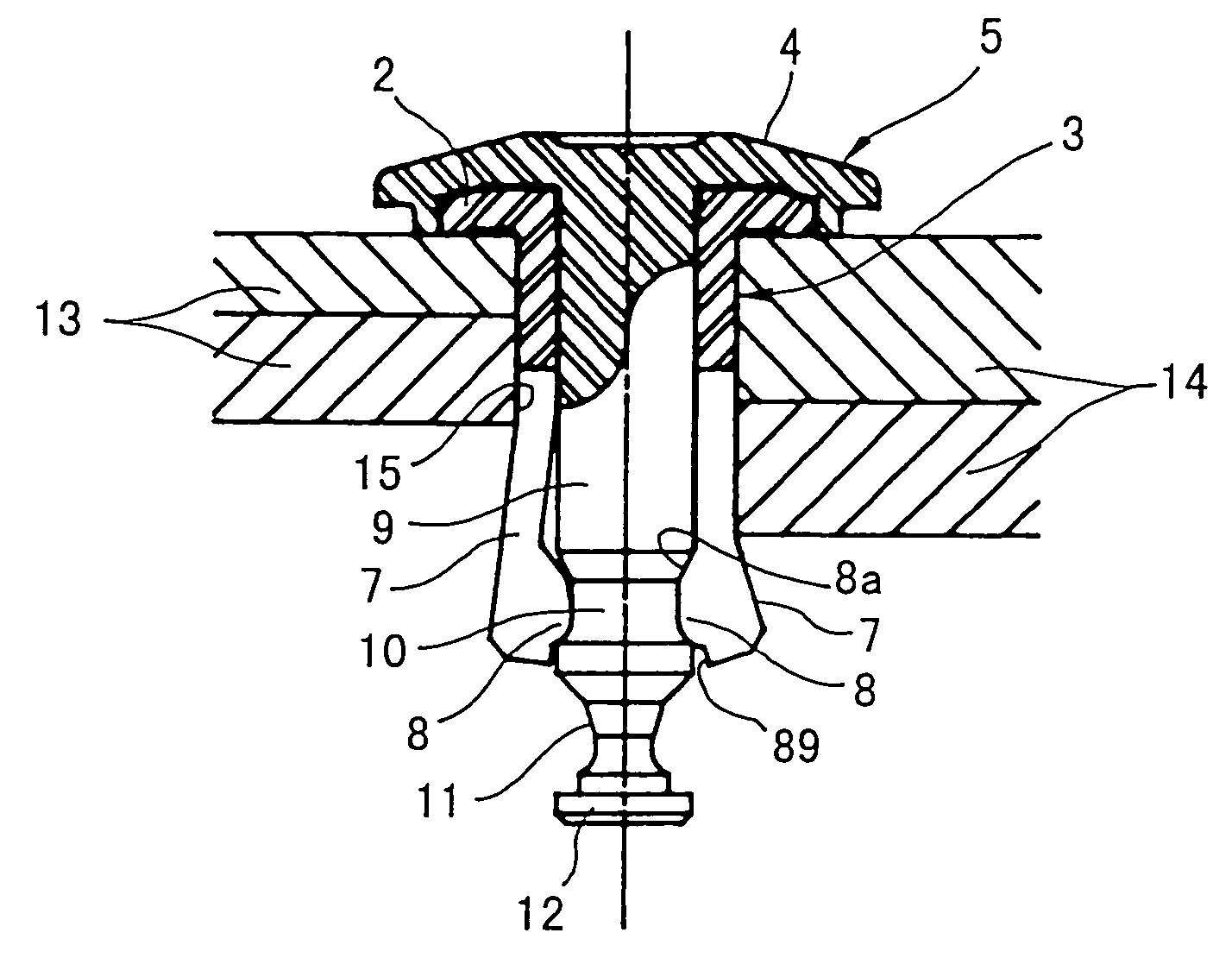
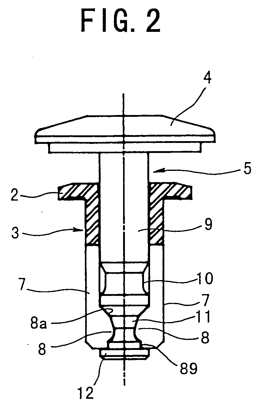
[0060] shown in FIG. 4, a plug 5 adapted to form a fastener 21 with a sleeve 3 has a greater length from its lower neck portion 11 to its flange portion 12 as a stop stepped portion.

third embodiment

[0061] shown in FIG. 5, a sleeve 18 adapted to form a fastener 31 with a plug 17 has a stop stepped portion 20 formed on the outer peripheral surface of its expanding portion 19 and engaging the edge of a hole 15 opening on the rear side of counterpart stationary components 16, when the expanding portion is expanded, provided, however, that the counterpart components 16 to be fastened together and fixed have a specific total thickness. In any other aspect of construction, it is basically identical to what is shown in FIGS. 2 and 3. This embodiment has the advantage that the tightening force of the fastener 31 itself makes a more reliable fastening together of the counterpart stationary components 16.

[0062] The fourth embodiment shown in FIG. 6 is based on the third embodiment shown in FIG. 5, and has the advantage of serving also as a so-called wire path sleeve, since a plug 44 adapted to form a fastener 41 with a sleeve 18 has a hollow shank 9 defining an inner cylindrical portion...

fifth embodiment

[0063] FIGS. 7 to 12 show the present invention and illustrate a type including a screw member 22, while a fastener 51 itself is used as an anchor portion, as shown in FIG. 7. FIG. 8 is an exploded view showing the mutual relationship between the structural elements and FIGS. 9 and 10 show details of a sleeve 23 and a plug 24 alone, respectively. FIGS. 7, 11 and 12 are, however, each a combination of views showing different states in their right and left half portions, and their right half portions show the case in which the counterpart components to be fastened together have a large thickness, while their left half portions show the case in which the counterpart components to be fastened together have a small thickness.

[0064] As shown in FIGS. 7 to 10, the fastener 51 is formed by a hollow cylindrical sleeve 23 having a thin seating flange portion 25, a plug 24 in the form of a hollow stepped shank press fitted in the sleeve 23 and a screw 22 as a screw member adapted to be screwed...


PUM


Abstract

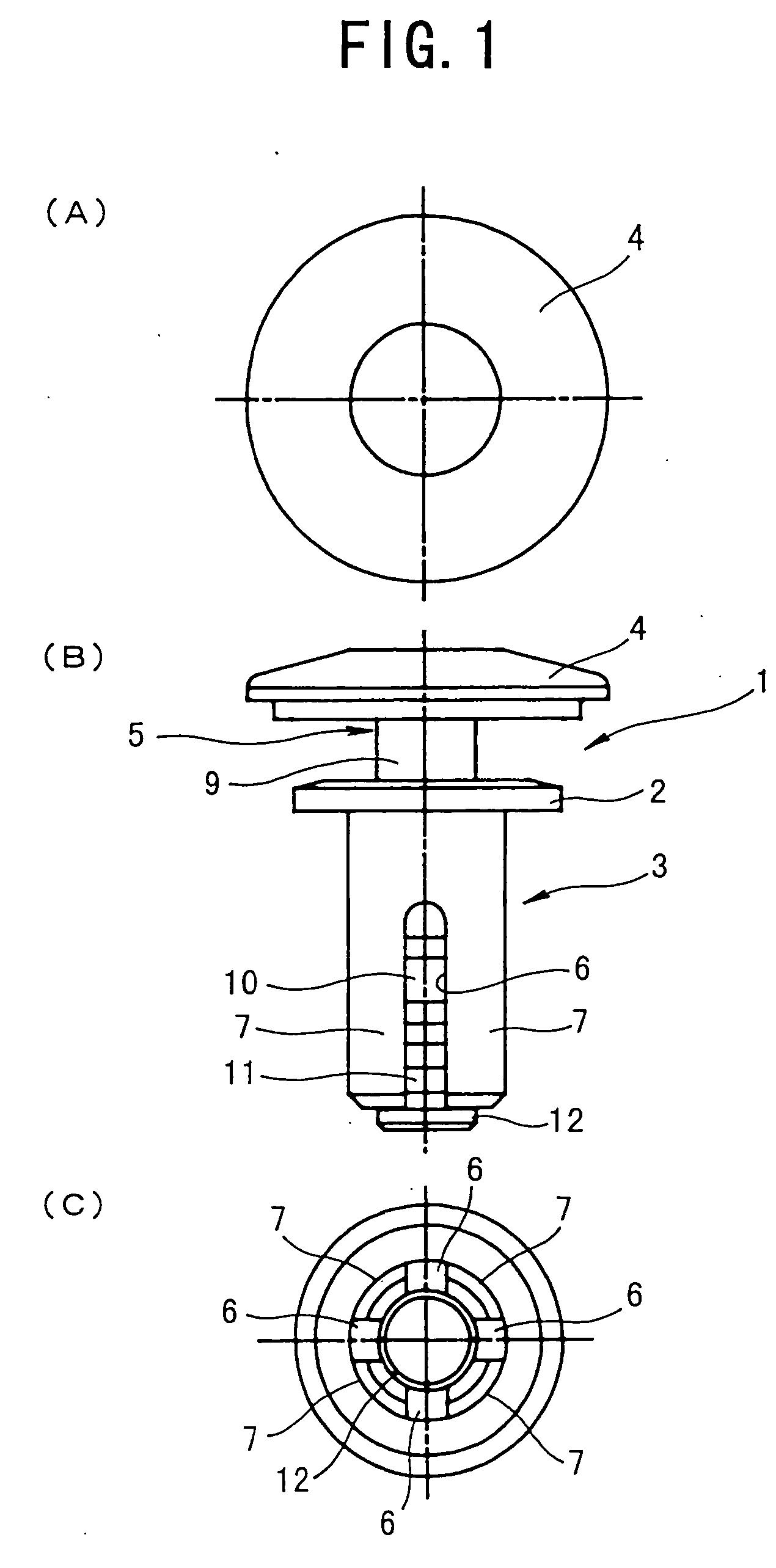
A fastener in which a sleeve 3 and a plug 4 are put into concavo-convex engagement both before and after execution to exert an effect of preventing separation between the two and an effect of preventing loosening therebetween after execution and which can be released by a single action during disassembling. Before execution, the sleeve 3 and the plug 4 press fitted therein are positioned by concavo-convex engagement between a fitting protrusion 8 on the inner periphery of an expanding portion 7 and a neck portion 11 of the plug 4. After execution, the fitting protrusion 8 on the inner periphery of the expanding portion 7 as expanded put into concavo-convex engagement with a neck portion 10 of the plug 4 again, thereby exerting an effect of stopping loosening between the two with respect to vibration, etc. During disassembling, a striking force is given to an end of the plug 4 to release the expanded state by a single action, allowing immediate pulling-away of the fastener 1.

Description

TECHNICAL FIELD [0001] The present invention relates to an improvement in an industrial fastener referred also to as a resin rivet or a push rivet, and more particularly, to a fastener structure which allows very easy engagement / coupling of two parts in sheet form, for example, irrespective of their material. BACKGROUND ART [0002] Various kinds of products have hitherto been proposed as this type of fastener. However, many are accompanied by difficulty when being removed by releasing their engagement / coupling, even though their engagement / coupling is possible by, for example, a single push or strike action. While it is, of course, necessary for fasteners to provide high impact and vibration resistances without getting loosened by receiving impact or vibration when they are used for, for example, fixing a circuit board for an electrical appliance, an OA machine or instrument, etc. or attaching an internal decoration material for an automobile, very easy releasing of the engagement / co...

Claims


Application Information

Patent Timeline
IPC IPC(8): F16B5/02F16B19/10F16B37/00F16B37/04
CPCF16B5/0258F16B37/041F16B37/005F16B19/1081
Inventor SATO, YOSHINORI
Owner ZEN KENCHIKU SEKKEI JIMUSHO TOKIOTOKYO
Learn More