Heat pipe heat dissipation structure

a heat dissipation structure and heat pipe technology, applied in indirect heat exchangers, lighting and heating apparatus, etc., can solve the problems of internal capillaries, internal capillaries, sintered metal powder or mesh capillaries, etc., to improve heat dissipation efficiency, reduce interface thermal resistance, and improve anti-gravity ability

Inactive Publication Date: 2013-08-22
ASIA VITAL COMPONENTS SHENZHEN CO LTD
View PDF7 Cites 25 Cited by
  • Summary
  • Abstract
  • Description
  • Claims
  • Application Information

AI Technical Summary

Benefits of technology

[0010]A primary object of the present invention is to provide a heat pipe heat dissipation structure, which has better heat transfer efficiency.
[0011]A further object of the present invention is to provide the above heat pipe heat dissipation structure, which has better anti-gravity ability and is able to reduce interface thermal resistance.
[0012]A still further object of the present invention is to provide the above heat pipe heat dissipation structure, which is able to bear greater thermal power impact per unit area.
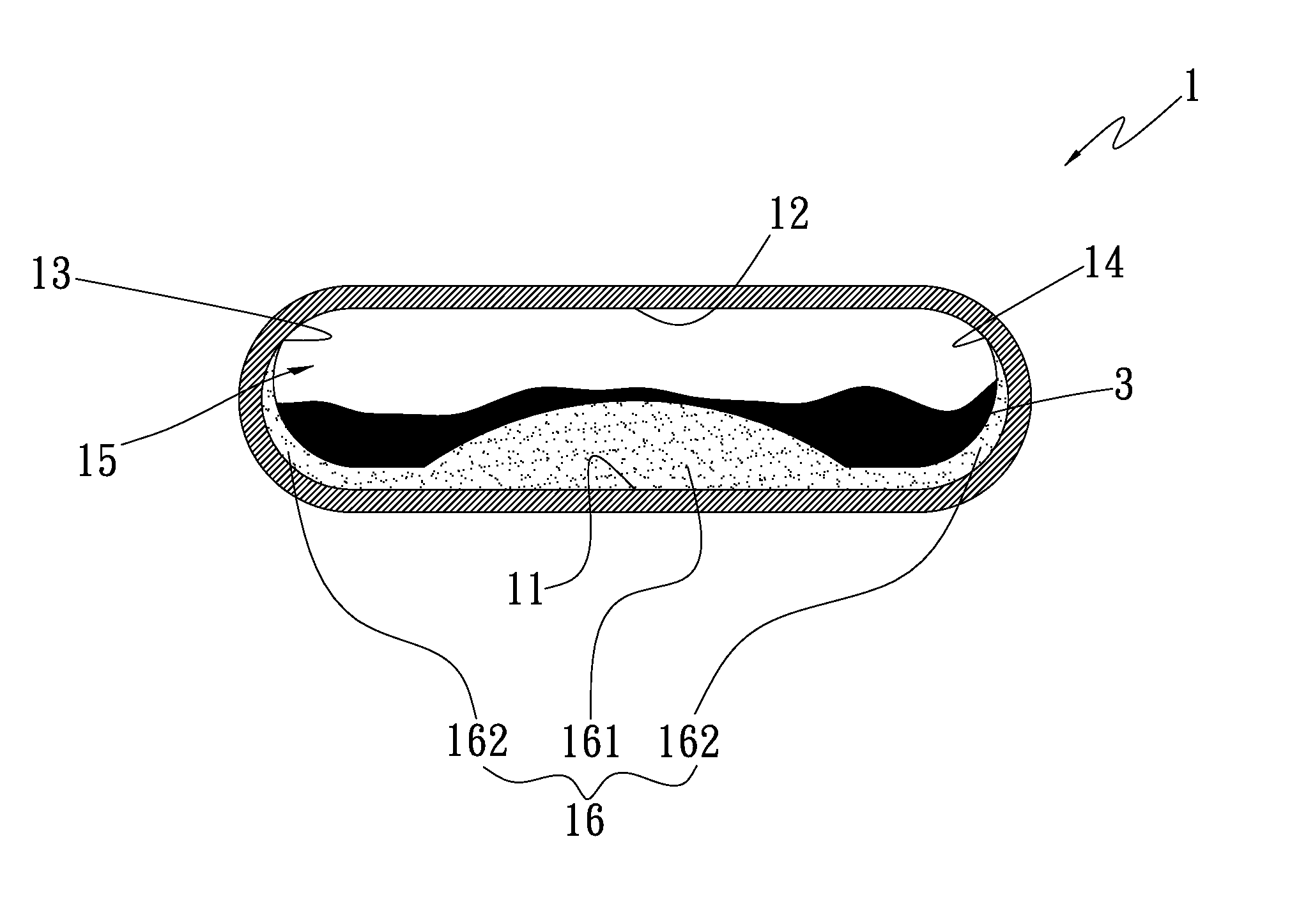
[0013]To achieve the above and other objects, the heat pipe heat dissipation structure of the present invention includes a main body and at least one first capillary structure. The main body has a first inner side, a second inner side opposite to the first inner side, a third inner side, a fourth inner side opposite to the third inner side and at least one chamber. A working fluid is filled in the chamber. The first capillary structure is disposed in the chamber. The first capillary structure includes a first section and a second section. The first section is formed on the first inner side. The second section extends from two sides of the first section along the adjacent third and fourth inner sides. The first section has a thickness larger than that of the second section. The first and second sections are respectively formed on the first, third and fourth inner sides of the main body. Accordingly, the vapor working fluid can fully freely flow within the chamber to advantageously achieve an excellent heat transfer efficiency, have better anti-gravity ability and reduce the pressure impedance. Moreover, the heat pipe heat dissipation structure is able to bear greater thermal power impact per unit area.

Problems solved by technology

However, this leads to another problem.
When compressing the flat-plate heat pipe, the capillary structure, (that is, the sintered metal powder or mesh capillary structure body) in the flat-plate heat pipe on two sides of the compressed faces is likely to be squeezed and damaged.
This will greatly deteriorate the heat transfer performance of the thin heat pipe or even make the thin heat pipe lose its function.
Moreover, although the flat-plate heat pipe can conduct the heat, after thinned and flattened, the internal capillary structure of the flat-plate heat pipe will have insufficient capillary attraction.
As a result, the anti-gravity thermal efficiency and heat transfer efficiency are poor.

Method used


Image

  • Heat pipe heat dissipation structure
  • Heat pipe heat dissipation structure
  • Heat pipe heat dissipation structure

Examples


Embodiment Construction

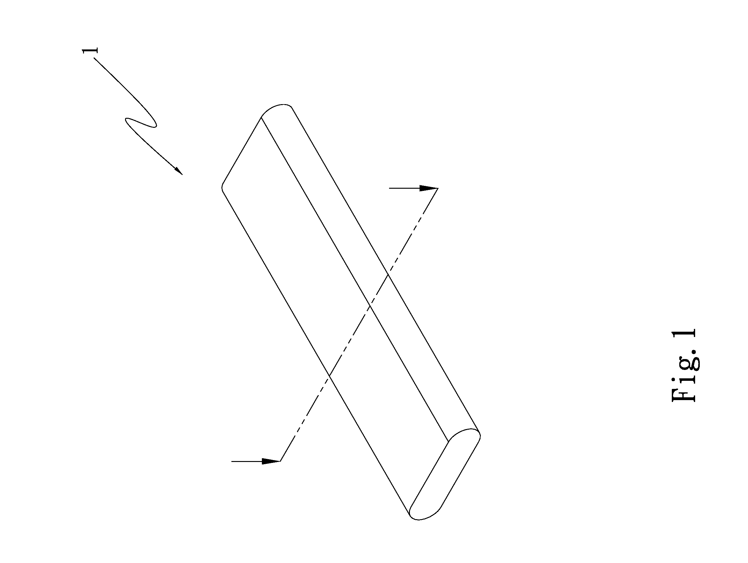
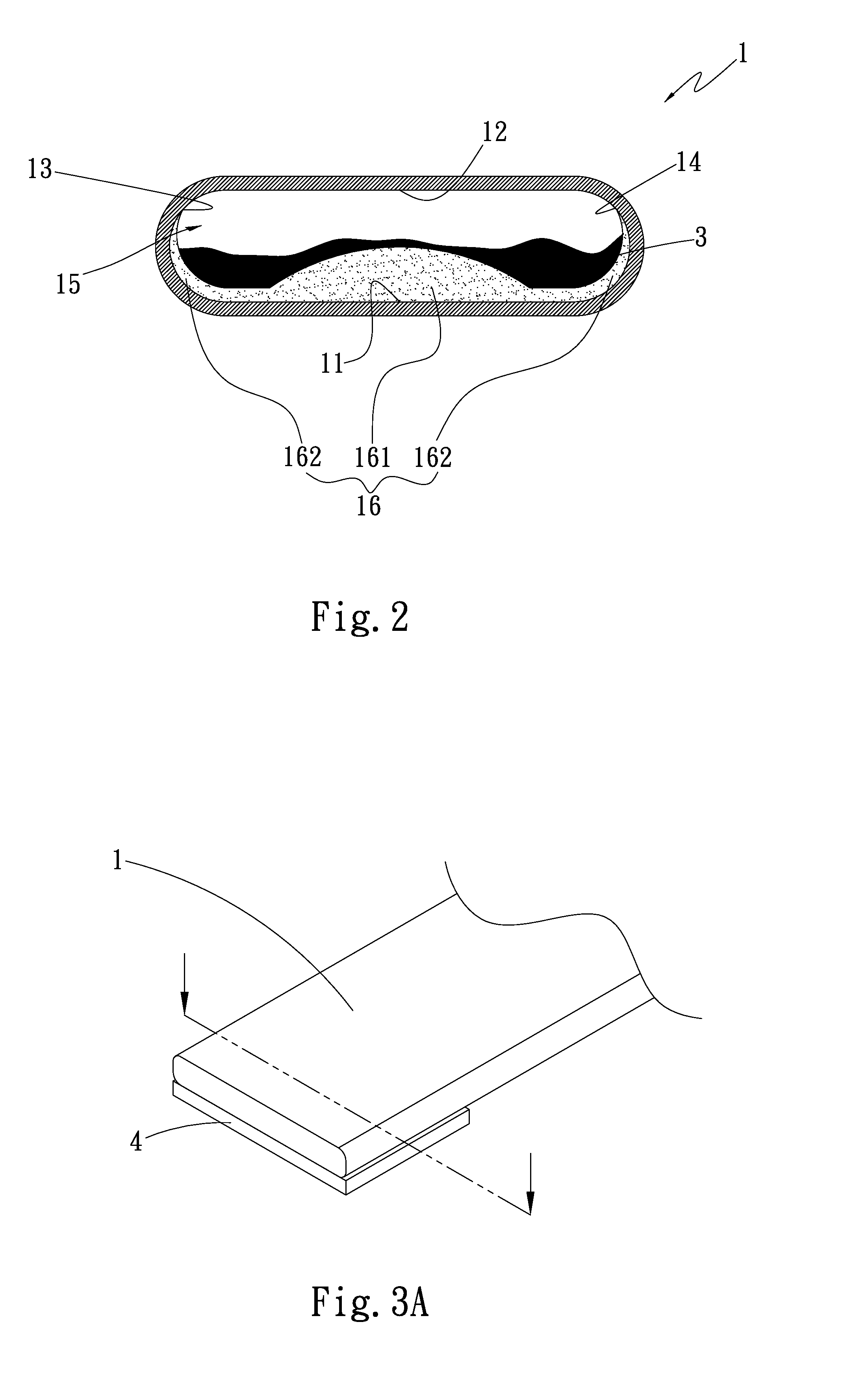
[0025]Please refer to FIGS. 1 and 2. FIG. 1 is a perspective view of a first embodiment of the heat pipe heat dissipation structure of the present invention. FIG. 2 is a sectional view of the first embodiment of the heat pipe heat dissipation structure of the present invention. According to the first embodiment, the heat pipe heat dissipation structure of the present invention includes a main body 1 and at least one first capillary structure 16. The main body 1 has a first inner side 11, a second inner side 12, a third inner side 13, a fourth inner side 14 and at least one chamber 15. The first inner side 11 is opposite to the second inner side 12, while the third inner side 13 is opposite to the fourth inner side 14. The first, second, third and fourth inner sides 11, 12, 13, 14 together define the chamber 15. A working fluid is filled in the chamber 15. The working fluid is selected from a group consisting of pure water, inorganic compound, alcohol, ketone, liquid metal, coolant a...


PUM


Abstract

A heat pipe heat dissipation structure includes a main body and at least one first capillary structure. The main body has a first inner side, a second inner side, a third inner side, a fourth inner side and at least one chamber filled with a working fluid. The first capillary structure is disposed in the chamber. The first capillary structure includes a first section disposed on the first inner side and a second section extending from two sides of the first section along the adjacent third and fourth inner sides. The first section has a thickness larger than that of the second section. The heat pipe heat dissipation structure has better heat transfer efficiency.

Description

BACKGROUND OF THE INVENTION[0001]1. Field of the Invention[0002]The present invention relates generally to a heat pipe heat dissipation structure, and more particularly to a heat pipe heat dissipation structure, which has better heat transfer efficiency and better anti-gravity ability and is able to reduce interface thermal resistance.[0003]2. Description of the Related Art[0004]There is a more and more obvious trend to miniaturization of all kinds of high-performance computers, intelligent electronic devices and other electrical equipments. To catch up this trend, the heat transfer components and heat dissipation components used in these devices have also been more and more miniaturized and thinned to meet the requirements of users.[0005]It is known that heat pipe is a heat transfer component with excellent thermal conductivity. The thermal conductivity of the heat pipe is several times to several tens times the thermal conductivity of copper, aluminum or the like. Therefore, the h...

Claims


Application Information

Patent Timeline
Patent Type & Authority Applications(United States)
IPC IPC(8): F28D15/04
CPCF28D15/046F28D15/0233
Inventor WU, CHUN-MING
Owner ASIA VITAL COMPONENTS SHENZHEN CO LTD
Why Eureka
Try Eureka