Apparatus for providing a near-IR emission suppressing/color enhancing accessory device for plasma display panels

a technology of near-ir emission suppression and accessory devices, which is applied in the direction of television systems, identification means, instruments, etc., can solve the problems of radio frequency interference, low luminous efficiency, and significant electrical noise, and achieve the effect of enhancing the performance of visual display units

Inactive Publication Date: 2000-05-23
OPTICAL COATING LAB
View PDF9 Cites 25 Cited by
  • Summary
  • Abstract
  • Description
  • Claims
  • Application Information

AI Technical Summary

Benefits of technology

It is an object of the present invention to provide methods and apparatus for providing accessory devi...

Problems solved by technology

A problem with PDPs is low luminous efficiency, a measure of the display output light luminance for a given input power.
The high power input, however, results in the emission of significant electrical noise including, specifically, radio frequency interference (RFI) due to the plasma discharges and significant infrared (IR) energy due to the plasma discharges and the heat generated within the panel.
The RFI and IR emissions may cause interference with other electronic equipment in the near vicinity of the PDP.
In particular, the IR radiation can interfere with remote control devices which typically operate at wavelengths in the nea...

Method used


Image

  • Apparatus for providing a near-IR emission suppressing/color enhancing accessory device for plasma display panels
  • Apparatus for providing a near-IR emission suppressing/color enhancing accessory device for plasma display panels

Examples


Embodiment Construction

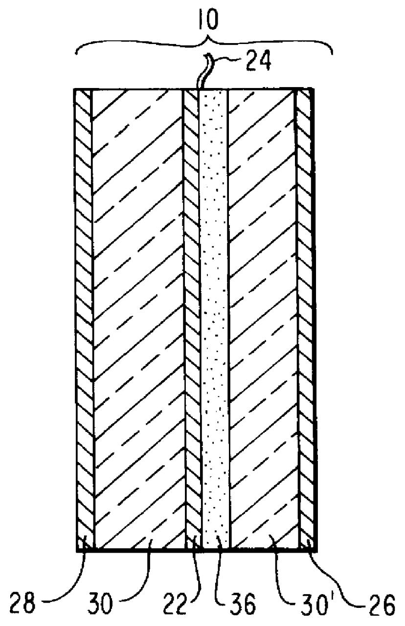
Preparation of Dyed Laminating Material

A formulation of two different IR-absorbing dyes, V63 and V102 (products of Epolin Inc.), and a color-balancing dye, CB Blue (product of Epolin Inc.), is prepared in the following manner: a 2:1 ratio (by weight) mixture of V102 and V63, respectively, is mixed with CB Blue dye in a ratio of 8:1 (by weight). The combination of dyes is then introduced into ethylene vinyl acetate (EVA) co-polymer in a concentration of 0.02% (by weight) that becomes dissolved and uniformly distributed. The EVA material, doped with the precisely formulated multiple-dye mixture, is then extruded into polymeric foil having a thickness of 12 micrometers.

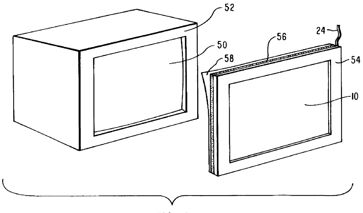
Preparation of Substrates and Assembly of Accessory Device

Glass having LoE.sup.2 .RTM. coating on one surface and an antireflection coating on the opposite side is cut to the desired size. A thin strip of adhesive conducting copper tape is placed around the periphery of the LoE.sup.2 .RTM. coating and is wrapped around t...


PUM

PropertyMeasurementUnit
Nanoscale particle sizeaaaaaaaaaa
Electrical conductivityaaaaaaaaaa
Coloraaaaaaaaaa

Abstract

The present invention is directed to apparatus for enhancing the performance of visual display units which utilize plasma display panels. More specifically, the present invention provides apparatus for providing an electrical noise suppressing/chromaticity enhancing accessory device for positioning in front of the viewing surface of a plasma display panel (PDP). In its most basic embodiment, the accessory device of the present invention comprises an optically selective coating providing high photopic transmittance, continuous high electrical conductivity for RFI shielding, and reflectivity specifically within the near-IR region. It also preferably includes a multiple-dye coating for selectively absorbing IR energy emissions and selectively balancing the chromaticity of the PDP display and a plastic substrate layer to provide impact resistance. The combination of the IR absorption and color-correction due to the multiple-dye coating and the near-IR reflectivity due to the optically selective coating surprisingly results in very good suppression of IR emissions from the PDP within the spectral range of about 800 to about 2500 nm and chromaticity enhancement while simultaneously maintaining good photopic transmittance.

Description

1. The Field of the InventionThe present invention is directed to methods and apparatus for enhancing the performance of visual display units which utilize plasma display panels. More specifically, the present invention provides methods and apparatus for providing an accessory device for positioning in front of the viewing surface of a plasma display panel that suppresses near-IR emissions in the range of about 800 to about 2500 nm while simultaneously providing good photopic transmittance and enhanced color and display readability.2. The Relevant TechnologyMany types of visual display units (VDUs) are known. A very useful type of flat panel display for VDUs utilizes a plasma display panel (PDP) to generate the visual image. PDPs consist of individual cells at the intersection of typically orthogonal electrically communicating address lines. The individual cells electrically communicate with a gas plasma. In a typical PDP, the conducting electrodes are patterned onto opposed surface...

Claims


Application Information

Patent Timeline
IPC IPC(8): G02B5/20G02B5/22G02B5/26G09F9/313H01J11/10H01J11/44
CPCB32B17/10036B32B17/10174B32B17/10339G02B5/208H01J11/10H01J11/44B32B17/10788H01J2229/8636
Inventor ZIEBA, JAROSLAWSEESER, JAMES W.CUMBO, MICHAEL J.BEAUCHAMP, WILLIAM T.SCANLON, ROBERT T.HRUSKA, CURTIS R.
Owner OPTICAL COATING LAB
Why Eureka
Try Eureka