
Method and apparatus for measuring the relative position of a first and a second alignment mark

a technology of alignment marks and relative positions, which is applied in the field of methods and apparatus for measuring the relative position of first and second alignment marks, can solve the problems of large shift of moiré patterns

Inactive Publication Date: 2005-06-09
ASML NETHERLANDS BV
View PDF3 Cites 38 Cited by
  • Summary
  • Abstract
  • Description
  • Claims
  • Application Information

AI Technical Summary

Benefits of technology

[0023] This method makes it possible to measure the relative position of two alignment marks without the need of a reference alignment mark.
[0026] According to an embodiment of the invention, the second alignment mark is a latent alignment mark. If the projection of the mark results in a latent mark, i.e., a mark that is visible without further post processing, such as a post-exposure-bake, the alignment can be done in the exposure unit of the lithographic projection apparatus. In that case the alignment can be checked without further processing of the substrate. This also makes it possible to first project the second alignment mark, check the alignment and only then project the patterned beam.

Problems solved by technology

An overlay error in the relative positioning of the substrate alignment mark and the resist alignment mark results in a shift of the Moiré pattern.
But, as will be understood by a person skilled in the art, the shift of the Moiré pattern is larger than the actual overlay error.
Thus, a small overlay error results in a larger shift of the Moiré pattern.
However, the alignment system described above, has the disadvantage that it requires the presence of a reference mark.

Method used


Image

  • Method and apparatus for measuring the relative position of a first and a second alignment mark
  • Method and apparatus for measuring the relative position of a first and a second alignment mark
  • Method and apparatus for measuring the relative position of a first and a second alignment mark

Examples


Embodiment Construction

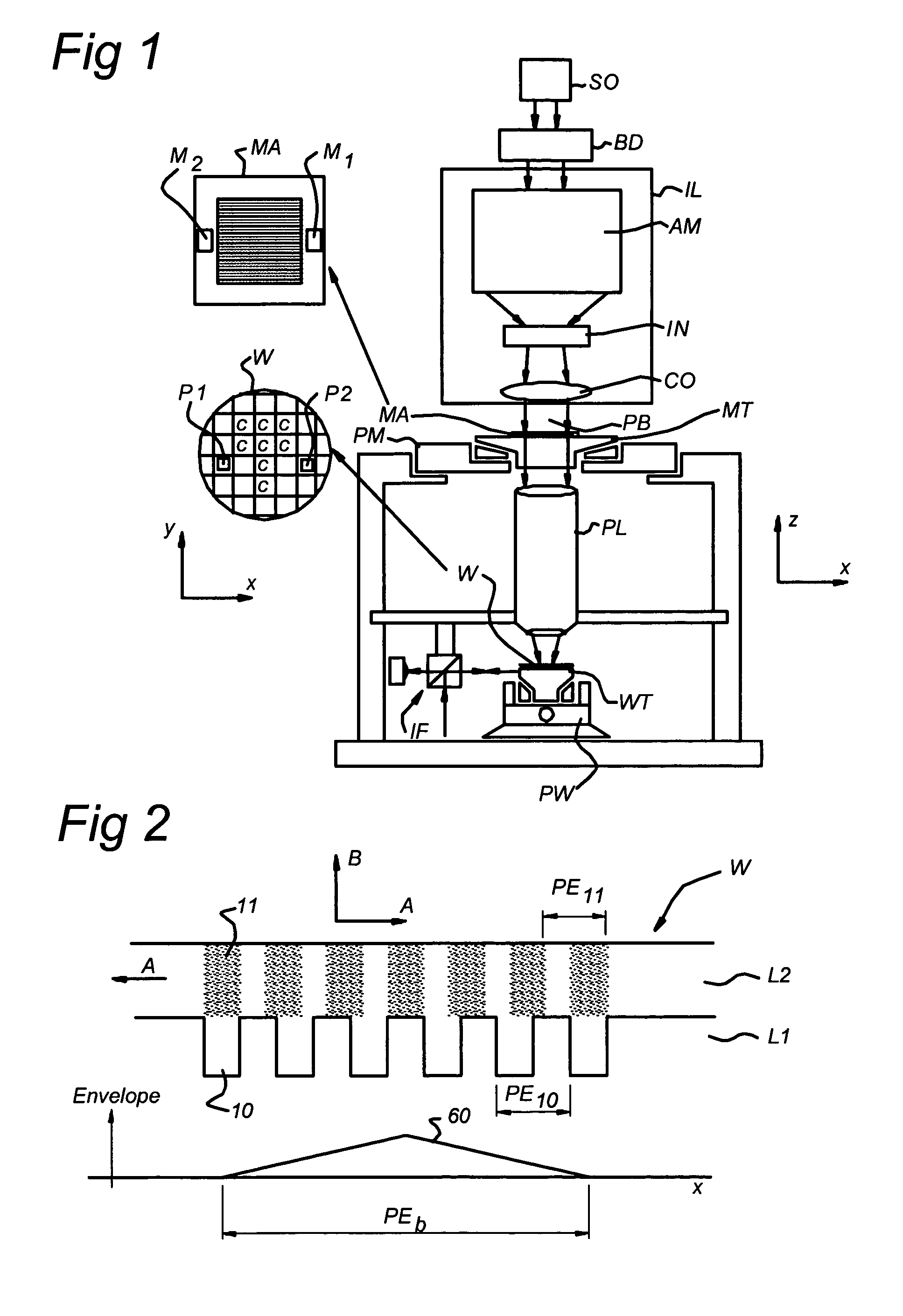
[0053]FIG. 1 schematically depicts a lithographic apparatus according to a particular embodiment of the invention. The apparatus comprises: [0054] an illumination system (illuminator) IL for providing a projection beam PB of radiation (e.g., UV radiation or EUV radiation). [0055] a first support structure (e.g., a mask table) MT for supporting patterning means (e.g., a mask) MA that is coupled to first positioning means PM for accurately positioning the patterning means with respect to item PL; [0056] a substrate table (e.g., a wafer table) WT for holding a substrate (e.g., a resist-coated wafer) W and coupled to second positioning means PW for accurately positioning the substrate with respect to item PL; and a projection system (e.g., a refractive projection lens) PL for imaging a pattern imparted to the projection beam PB by patterning means MA onto a target portion C (e.g., comprising one or more dies) of the substrate W.

[0057] As here depicted, the apparatus is of a transmissiv...


PUM


Abstract

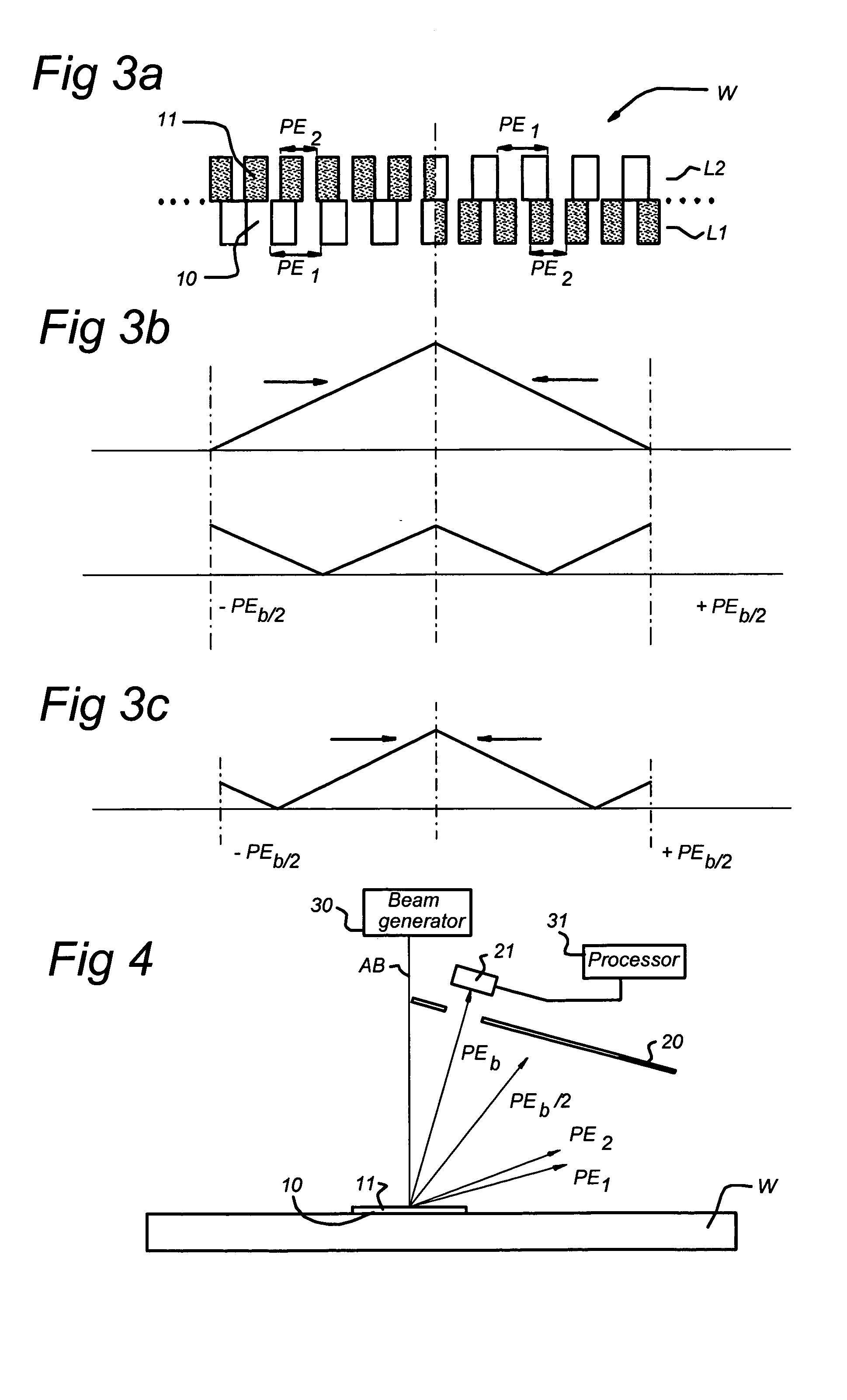
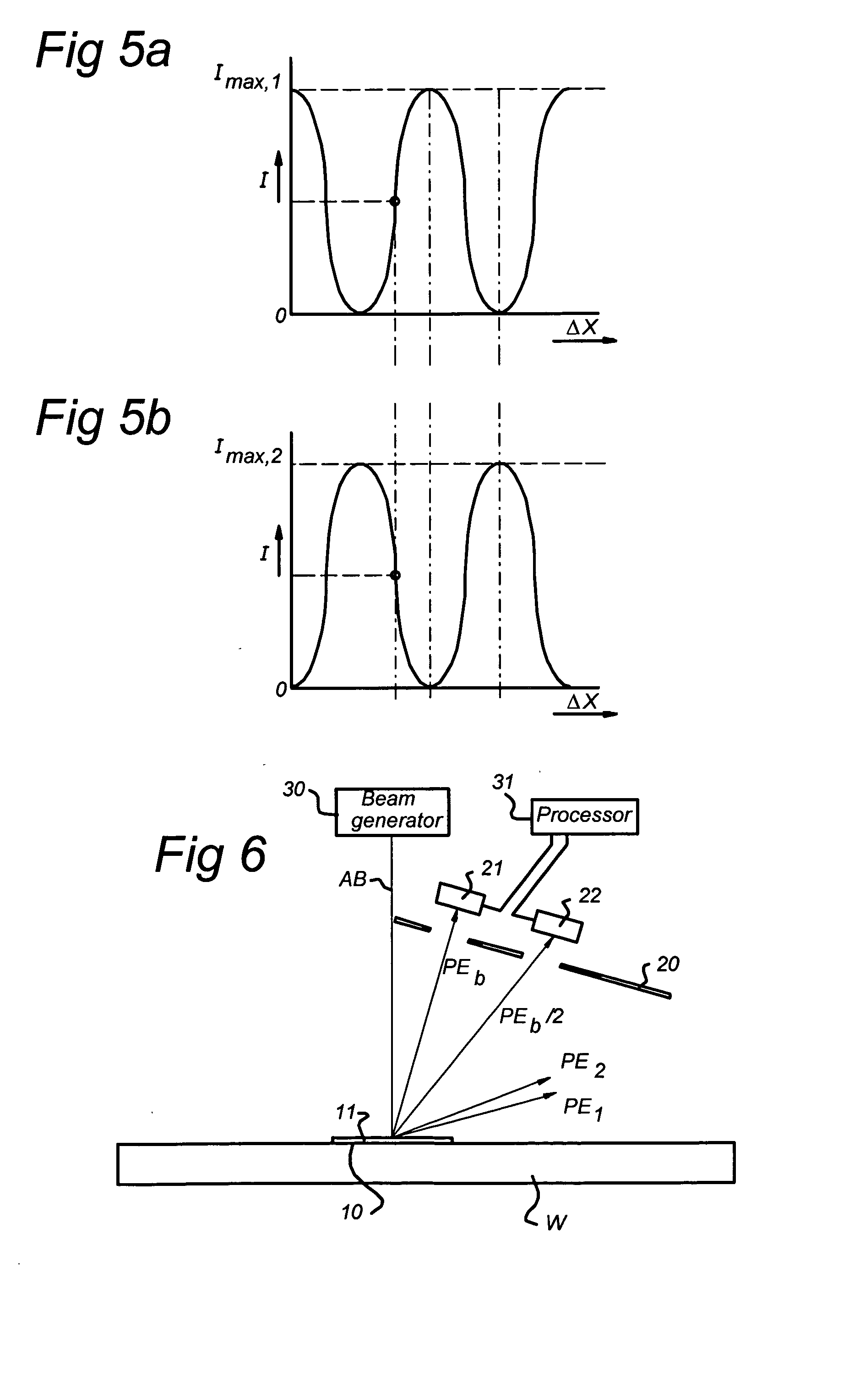
The invention relates to a method for measuring the relative position of a first and a second alignment mark on a substrate. The first alignment mark comprises a periodic structure having a first portion with a first periodicity (PE1) and an adjacent second portion with a second periodicity (PE2). The second alignment mark (11) comprises a periodic structure having a first portion with the second periodicity (PE2) and an adjacent second portion with the first periodicity (PE1). The first and second alignment marks are arranged such that the first portions are substantially located one over the other and the second portions are substantially located one over the other. The method further comprises generating a Moiré pattern from the alignment marks and determining the relative positions of the first and second alignment marks based on the periodicity of the Moiré pattern.

Description

CROSS-REFERENCE TO RELATED APPLICATIONS [0001] This Application claims priority from European Patent Application No. 03078479.7 filed Nov. 4, 2003, which is incorporated herein by reference in its entirety. FIELD OF THE INVENTION [0002] The present invention relates to a method for measuring a relative position of a first alignment mark and a second alignment mark on a substrate, wherein the alignment marks are placed in a first direction that is substantially along the surface of the substrate. The present invention further relates to a device manufacturing method. A substrate is provided with at least two alignment marks according to the invention and an apparatus for applying the method according to the invention. [0003] The present invention further relates to a lithographic projection apparatus that includes a radiation system for supplying a projection beam of radiation, a support structure for supporting patterning means, the patterning means serving to pattern the projection...

Claims


Application Information

Patent Timeline
IPC IPC(8): G01B11/00G01B11/27G03F7/20G03F9/00H01L21/027H01L23/544
CPCG01B11/27G03F7/70633G03F9/7049G03F9/7076H01L2924/0002H01L23/544H01L2924/00
Inventor MONSHOUWER, RENE
Owner ASML NETHERLANDS BV
Learn More