Polishing head and polishing apparatus

Active Publication Date: 2005-06-09
GLOBALWAFERS JAPAN
View PDF2 Cites 7 Cited by
  • Summary
  • Abstract
  • Description
  • Claims
  • Application Information

AI Technical Summary

Benefits of technology

[0031] The present invention has been made in consideration of the above circumstances, and has as its object to provide a polishing apparatus which can accurately polish the surface of an obje

Problems solved by technology

That is, circumferential droop disadvantageously occurs.
For this reason, the wafer polishing apparatus having the configuration disadvantageously increases the load on an operator.
For this reason, a contact pressure acting between the central portion of the wafer U and the polishing pad is lower than that of the edge po

Method used


Image

  • Polishing head and polishing apparatus
  • Polishing head and polishing apparatus
  • Polishing head and polishing apparatus

Examples


Example

[0064] A first embodiment of the present invention will be described below with reference to FIGS. 1 to 3.

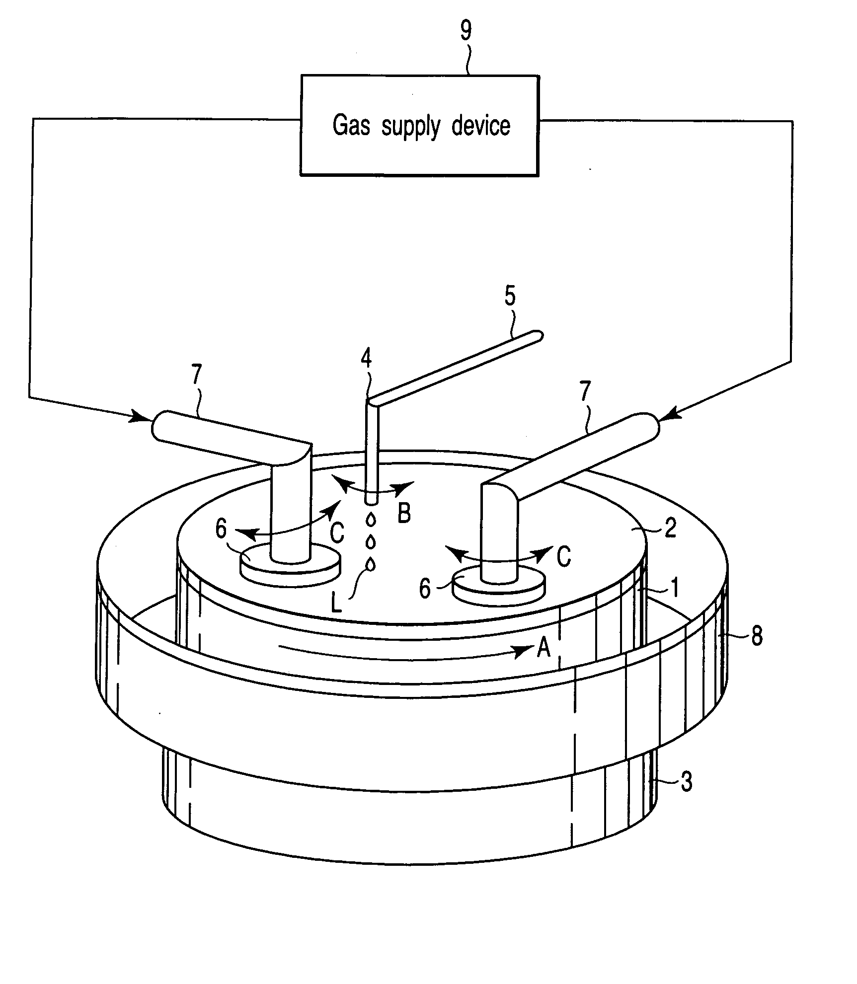
[0065]FIG. 1 is a perspective view of a wafer polishing apparatus according to the first embodiment of the present invention.

[0066] As shown in FIG. 1, the wafer polishing apparatus (polishing apparatus) has a machine platen 1. The machine platen 1 is formed in the form of a disk. A polishing pad 2 is stuck on the upper surface of the machine platen 1. The material of the polishing pad 2 is appropriately selected depending on the material of a polishing layer of a wafer U. A drive shaft (not shown) of a drive device 3 is connected to the lower portion of the machine platen 1. The drive shaft is rotated to make it possible to rotate the machine platen 1 in a direction indicated by an arrow A.

[0067] A polishing liquid supply pipe 4 is arranged above the polishing pad 2 stuck on the machine platen 1 to oppose the polishing pad 2. The polishing liquid supply pipe 4 is supported b...

Example

[0093] A second embodiment of the present invention will be described below with reference to FIG. 4.

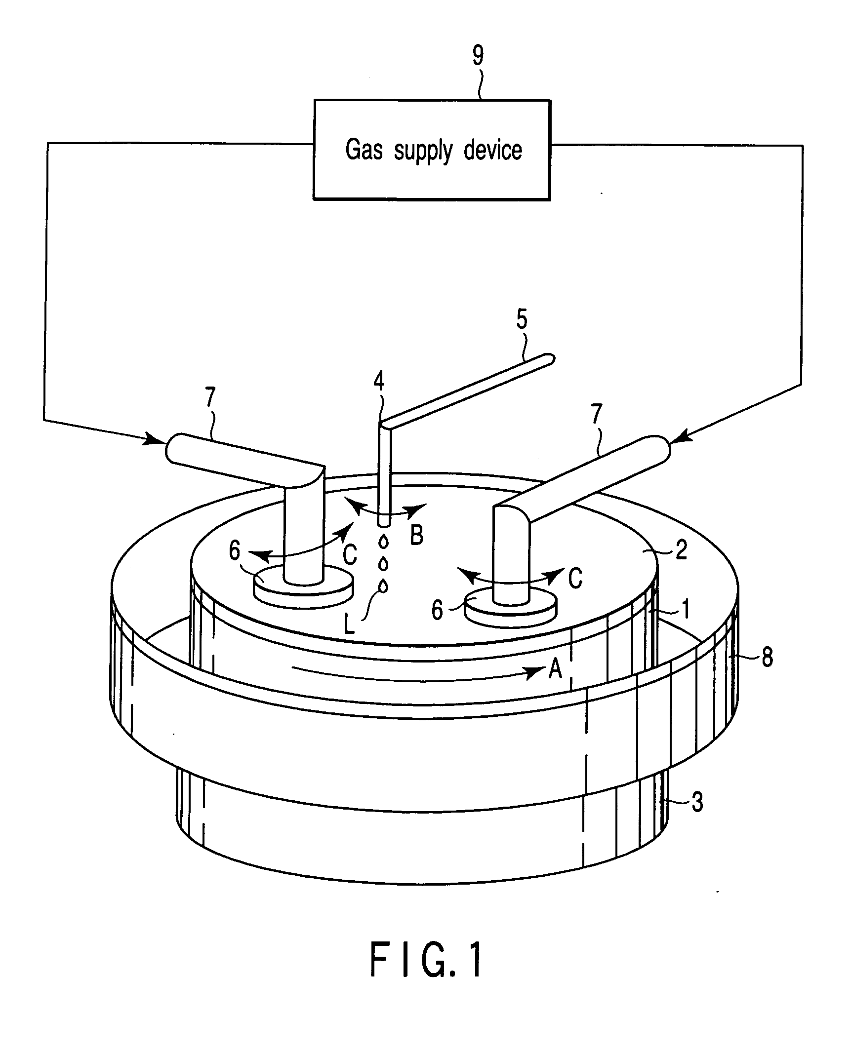
[0094]FIG. 4 is a sectional view of a polishing head according to the second embodiment of the present invention.

[0095] As shown in FIG. 4, an alignment member 23A according to the embodiment is arranged on the outer peripheral portion of the upper surface of a support plate 13. The alignment member 23A is in contact with the inner peripheral portion of the lower surface of a first film-like member 16 to prevent the inner peripheral portion of the first film-like member 16 from bending downward at a portion projecting on the outside of the support plate 13 in the radial direction.

[0096] In this manner, even though the alignment member 23A is arranged on the support plate 13, the plurality of alignment members 23A having different outer diameters are prepared, and a alignment member 23A having an optimum outer diameter is selected from the plurality of alignment members 23A, so tha...

Example

[0097] A third embodiment of the present invention will be described below with reference to FIG. 5.

[0098]FIG. 5 is a plan view of an alignment member according to the third embodiment of the present invention.

[0099] As indicated by Sa and Sb in FIG. 5, an alignment member 23B is constituted by two ring-like members 23b having the same shapes. These ring-like members 23b are detachably arranged on the head body 10 in such a state that the ring-like members 23b overlap. On the inner peripheral portion of each member 23b, a plurality of projecting portions 31 which prevent the outer peripheral portion of a first film-like member 16 from bending downward are arranged at predetermined intervals in the circumferential direction.

[0100] As indicated by Sc in FIG. 5, the two members 23b are caused to coaxially overlap each other, and the alignment member 23 are shifted in the circumferential direction, so that a support area of the first film-like member 16 supported by the alignment mem...


PUM


Abstract

A polishing head includes a head body, a first recessed portion formed in the lower surface of the head body, a support plate which can be moved up and down in the first recessed portion, a first film-like member in which a first space is formed between the upper surface of the support plate and the head body, a second recessed portion formed in a lower surface of the support plate, a second film-like member, in which a second space is formed between the second film-like member and the support plate, and which holds a wafer on the lower, a communicating hole which is formed in the support plate to communicate the first space with the second space, and a gas supply device which increases pressures in the first and second spaces with a fluid to equal pressures to bring the object into press contact with the polishing pad.

Description

CROSS-REFERENCE TO RELATED APPLICATIONS [0001] This application is based upon and claims the benefit of priority from prior Japanese Patent Application No. 2003-407755, filed Dec. 5, 2003, the entire contents of which are incorporated herein by reference. BACKGROUND OF THE INVENTION [0002] 1. Field of the Invention [0003] The present invention relates to a polishing head and a polishing apparatus to polish the surface of an object to be processed such as a wafer. [0004] 2. Description of the Related Art [0005] For example, wafer manufacturing steps include a polishing step of mirror-finishing the surface of a wafer. In this step, a wafer polishing apparatus brings a wafer into press contact with the surface of a rotating polishing pad to polish the surface of the wafer. [0006] This wafer polishing apparatus has a polishing table rotated by a drive shaft. A polishing pad is arranged on the upper surface of the polishing table, and a polishing head which rotates while holding a wafer ...

Claims


Application Information

Patent Timeline
IPC IPC(8): B24B37/005B24B37/04B24B37/30B24B37/32H01L21/304
CPCB24B37/30B24B37/11B24B37/04H01L21/304
Inventor MASUNAGA, TAKAYUKIOOFUCHI, SHINOBUISOGAI, HIROMICHIKOJIMA, KATSUYOSHI
Owner GLOBALWAFERS JAPAN
Why Eureka
Try Eureka