Method and apparatus for determining an ultrasound fluid flow centerline

a centerline and ultrasound technology, applied in the field of ultrasonic data processing, can solve the problems of difficult to get a good approximation of the angle using, the true velocity of the ultrasound, and the use of both hands and eyes by the sonographer, so as to achieve the effect of propagating and receiving ultrasound energy

Inactive Publication Date: 2005-06-09
PHYSIOSONICS
View PDF35 Cites 96 Cited by
  • Summary
  • Abstract
  • Description
  • Claims
  • Application Information

AI Technical Summary

Benefits of technology

[0008] The disadvantages and limitations of prior art ultrasound apparatus and methods are overcome by the present invention which includes, a method for determining the location of an effective center of a fluid flow in a vessel using an ultrasound apparatus with a transducer array for propagating and receiving ultrasound energy. Ultrasound energy is propagated along an axis of propagation Z, which can be described by a spacial coordinate system (x, y, z) in which the dimension z is in the same direction as the axis of propagation Z. The ultrasound energy projects upon the vessel defining a set of coordinates in the spacial coordinate system...

Problems solved by technology

A drawback of this manual approach is that even for a skilled sonographer, the resultant true velocity is only approximate.
Another drawback is that the sonographer needs to use both hands and eyes to obtain a single measurement.
It is difficult to get a good approximation of the angle θ using this two hand manual approach.
However, it is difficult, if not impossible, to obtain other desirable parameters such as volume flow (the amount of blood flowing through a given cross-sectional area of the blood vessel) and lumen area (the total area of a cross section perpendicular to the blood vessel at a given point) with the use of this method.

Method used


Image

  • Method and apparatus for determining an ultrasound fluid flow centerline
  • Method and apparatus for determining an ultrasound fluid flow centerline
  • Method and apparatus for determining an ultrasound fluid flow centerline

Examples


Embodiment Construction

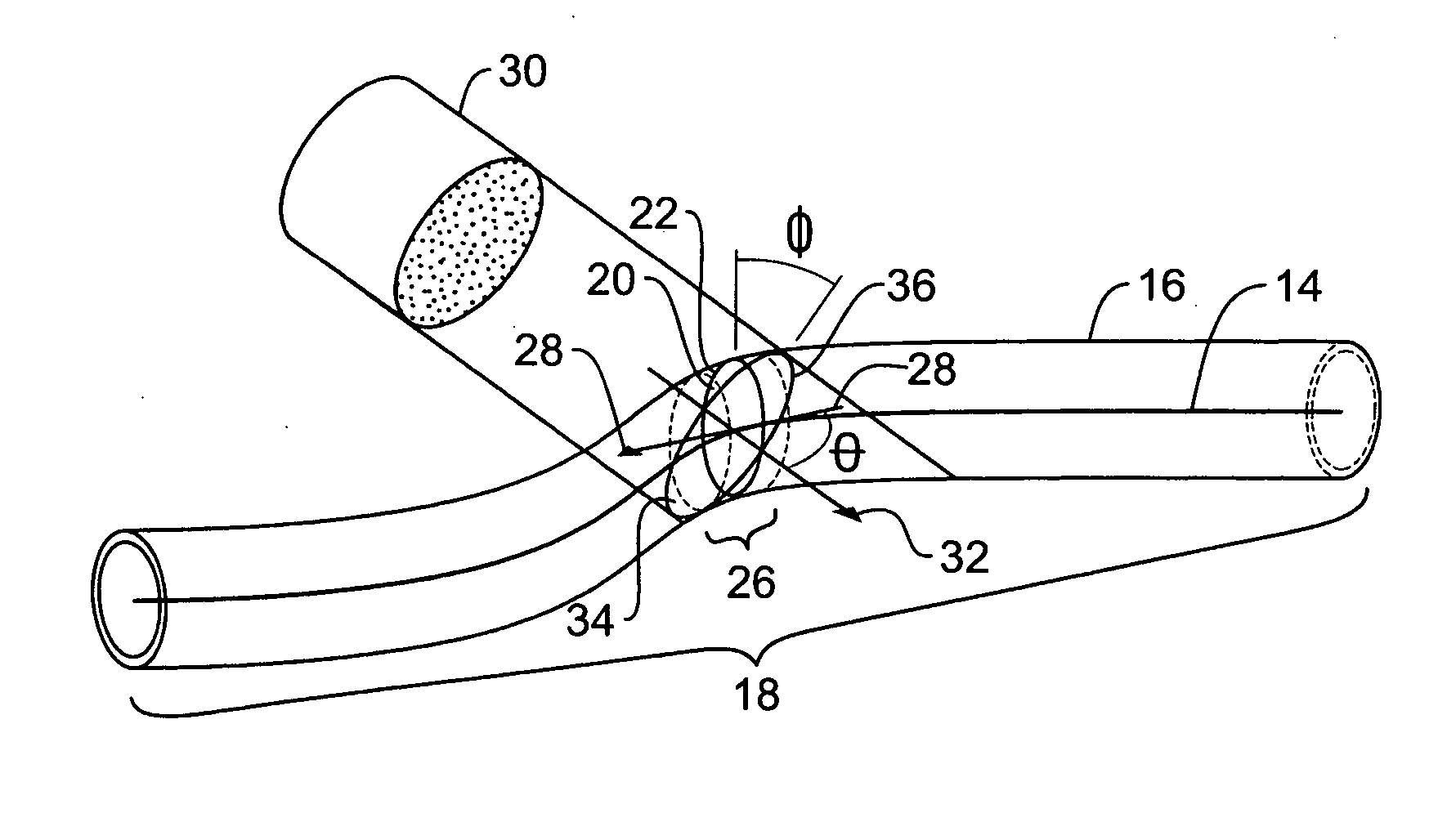
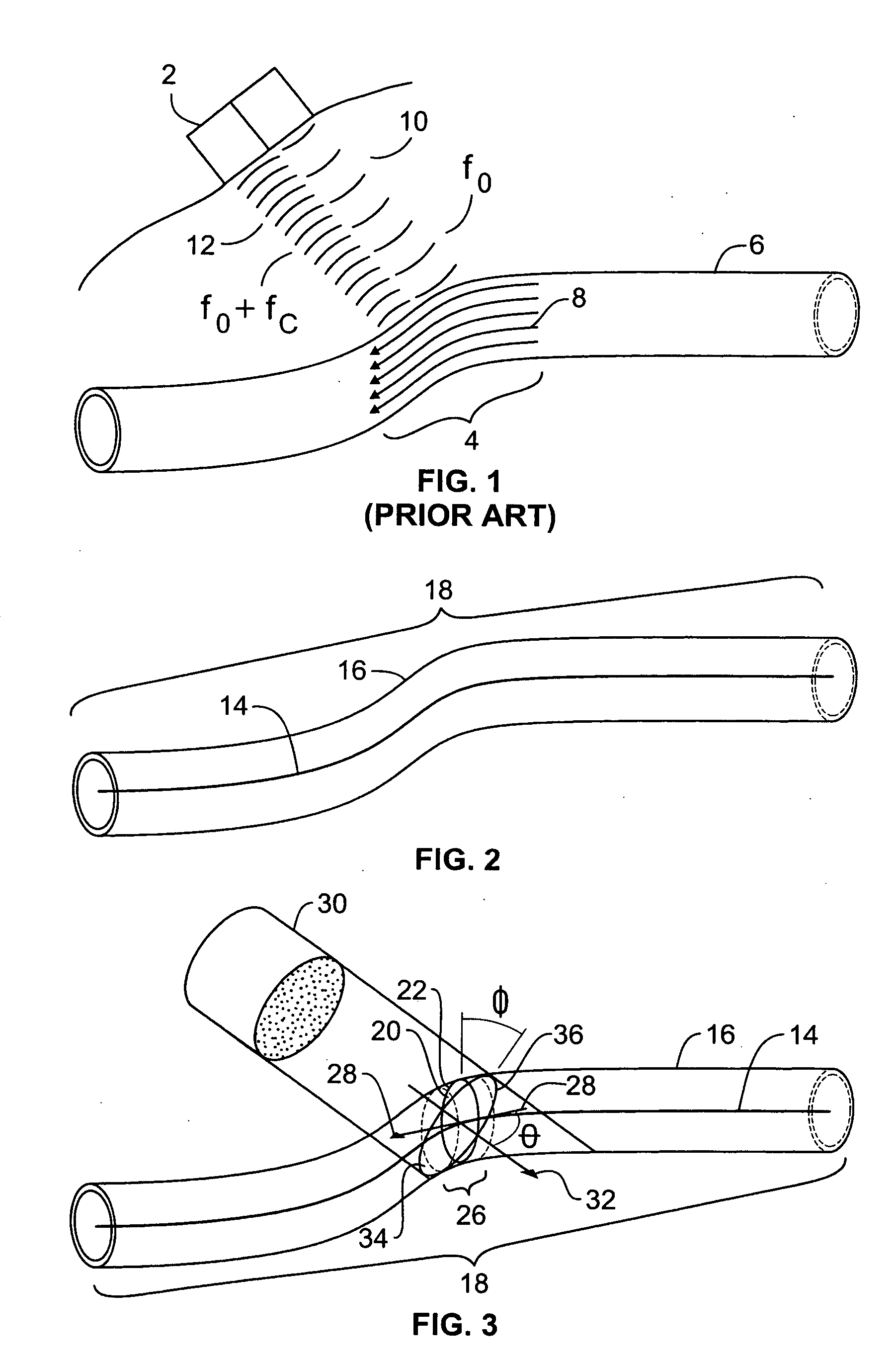
[0027] With reference to FIGS. 2 and 3, a centerline 14 is drawn through a vessel 16 (e.g. a blood vessel) within the body of a living being (e.g. a human) within the field of view 18 of an ultrasound probe (not shown). The centerline 14 is defined as a plurality of statistical “centers” of the vessel 16 throughout the field of view 18. The centerline 14 is derived from measured ultrasound parameters such as 4-D Power Doppler or 4-D color flow data. It can be, for instance, the mean (average), median (central value), or mode (location of maximum) of samples of ultrasound measurements taken over successive cross-sections of areas 20 along the vessel 16. The mean of a dimension x representing the x dimension in the coordinate system of the frame of reference of the ultrasound probe using a(x) as a density of some desirable ultrasound parameter is ∫xa(x)dx, provided that a(x) is normalized so that it integrates to unity. The median is the value x0 such that ∫-∞x0⁢a⁡(x)⁢ ⁢ⅆx=∫x0∞⁢a⁡(x)...


PUM


Abstract

A method and associated apparatus are disclosed for determining the location of an effective center of fluid flow in a vessel using an ultrasound apparatus. Ultrasound energy is propagated along an axis of propagation and projects upon the vessel. A Doppler-shifted signal reflected from the fluid in the vessel is received and a set of quantities expressed as a density is derived from the Doppler shifted signal for each of a set of coordinates, the density being a function of the Doppler shift in frequency associated with each of the coordinates. One of a mean, mode or median is calculated for each of the dimensions of the set of coordinates in conjunction with the density associated therewith. This calculation is repeated throughout the field of view of the vessel to define a centerline.

Description

CROSS-REFERENCE TO RELATED APPLICATION [0001] This application claims the benefit of U.S. Provisional Application Ser. No. 60 / 515,350 filed Oct. 29, 2003, the disclosure of which is incorporated herein by reference in its entirety.FIELD OF THE INVENTION [0002] The present invention relates to ultrasound data processing, and more particularly, to finding the attributes of fluid flow in a living body, such as ascertaining the speed, direction, and volume of a fluid flow in a vessel using ultrasound. BACKGROUND OF THE INVENTION [0003] Several techniques exist for locating an object using wave-propagation. In the fields of sonar, radar, ultrasound, and telecommunications, transmitting / receiving elements are placed in an array. Some or all of the elements of the array emit pulses of electromagnetic radiation or sound toward a target, and reflections of the wave pattern from the target are received at some or all of the elements. To receive the maximum amplitude (strongest signal) possibl...

Claims


Application Information

Patent Timeline
IPC IPC(8): A61BA61B8/00A61B8/02A61B8/06A61B8/12
CPCA61B8/06G01S15/8981A61B8/085G01S15/8988G01S15/8993G01S15/8984
Inventor ABEND, KENNETHSTEIN, ALAN
Owner PHYSIOSONICS
Why Eureka
Try Eureka