Broadcast receiving apparatus, control method and program therefor
a technology for broadcasting receiving apparatus and control method, which is applied in broadcast information monitoring, selective content distribution, television systems, etc., can solve the problems of battery capacity deficiency, prior technology does not have measures against wireless transmission between the receiving portion and the display portion of the television receiver,
- Summary
- Abstract
- Description
- Claims
- Application Information
AI Technical Summary
Benefits of technology
Problems solved by technology
Method used
Image
Examples
first embodiment
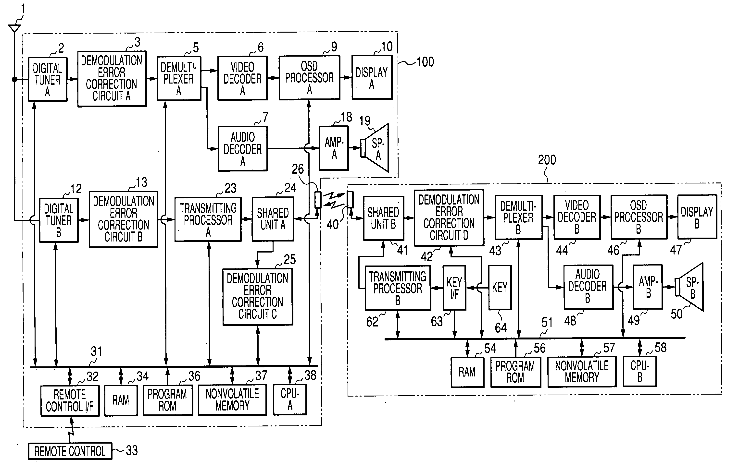
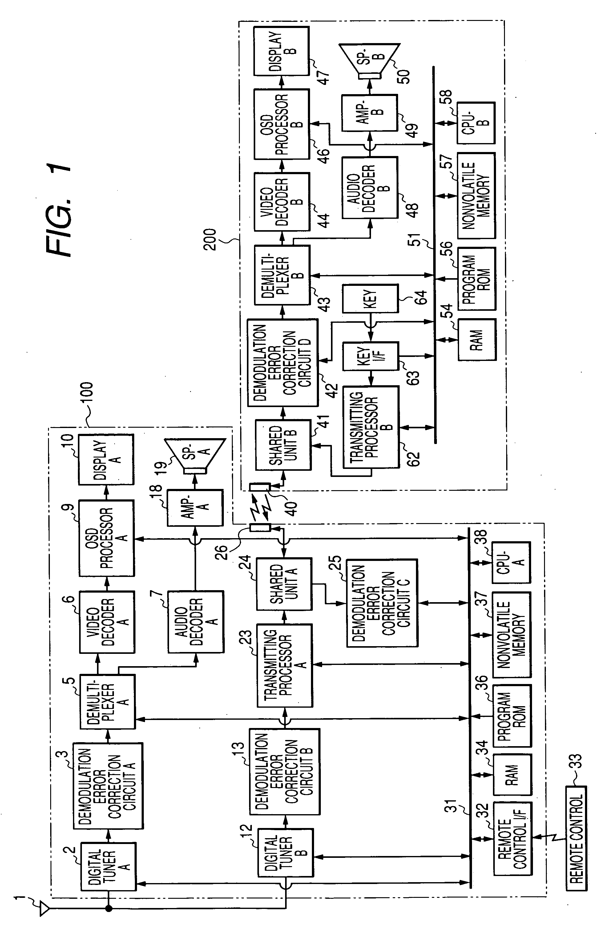
[0041]FIG. 1 is a block diagram showing a configuration of a parent / child television system constituting a first embodiment of the present invention.
[0042] Referring to FIG. 1, a parent / child television system is provided with an antenna 1 for receiving a digital broadcast wave transmitted from a broadcasting station, a parent device A100 for executing a video display and an audio reproduction based on the digital broadcast wave received by the antenna 1, a child device B200 for executing a video display and an audio reproduction based on a transport stream data outputted from the parent device A100, and a remote control 33 for various instructions to the parent / child television system by a user.
[0043] In the present embodiment, a digital broadcasting receivable by the parent / child television system is based on a digital broadcasting system standards of DVB (digital video broadcasting), in which a video signal and an audio signal are respectively transmitted from the broadcasting ...
second embodiment
[0074]FIG. 4 is a block diagram showing a configuration of a parent / child television system constituting a second embodiment of the present invention.
[0075] The present embodiment is different from the foregoing first embodiment in that the child device B200 is provided with a battery 70 and battery watching means 71 (watching means). Other components of the present embodiment are similar to those in the first embodiment (FIG. 1), thus represented by corresponding numbers and are not explained further.
[0076] At first, there will be explained differences of the present embodiment from the first embodiment. The child device B200 is battery drivable, and is rendered more widely movable by utilizing the battery 70 as a power source for the entire child device. A remainder charge of the battery 70 is constantly watched by the battery watching unit 71, and is made available to the CPU-B 58 of the child device B200.
[0077] The CPU-A 38 of the parent device A100 executes a process of a pa...
third embodiment
[0087]FIGS. 7A and 7B are block diagrams showing a configuration of a parent / child television system constituting a third embodiment of the present invention.
[0088] The present embodiment is different from the foregoing first embodiment in that the parent device A100′ is provided with switches 4, 14, 15, a hard disk drive (HDD) interface 16 and a HDD 17, and the child device B200 is provided with a battery 70 and battery watching means 71 (watching means). Other components of the present embodiment are similar to those in the first embodiment (FIG. 1), thus represented by corresponding numbers and are not explained further.
[0089] At first, there will be explained differences of the present embodiment from the first embodiment, with reference to FIGS. 7A and 7B. The HDD 17 of the parent device A100 is used for recording and play the transport stream data received in the parent device A100′. The HDD interface 16 controls the HDD 17 according to an instruction from the CPU-A 38. The ...
PUM
 Abstract
Description
Claims
Application Information
 - R&D
- Intellectual Property
- Life Sciences
- Materials
- Tech Scout
- Unparalleled Data Quality
- Higher Quality Content
- 60% Fewer Hallucinations
Browse by: Latest US Patents, China's latest patents, Technical Efficacy Thesaurus, Application Domain, Technology Topic, Popular Technical Reports.
© 2025 PatSnap. All rights reserved.Legal|Privacy policy|Modern Slavery Act Transparency Statement|Sitemap|About US| Contact US: help@patsnap.com


