Laundry dryer

a technology for drying racks and dryers, applied in the field of laundry dryers, can solve the problems of increasing power consumption, easy damage of laundry, and special laundry, such as rubber shoes, which cannot be treated in the same manner, so as to reduce the time necessary for drying the laundry and reduce the power consumption of the laundry dryers.

Inactive Publication Date: 2005-06-16
LG ELECTRONICS INC
View PDF4 Cites 56 Cited by
  • Summary
  • Abstract
  • Description
  • Claims
  • Application Information

AI Technical Summary

Benefits of technology

[0016] In addition, since the drying operation need not be performed several times, the power consumption o

Problems solved by technology

Specifically, when the clothes are dried in the laundry dryer, they may be easily damaged.
In addition, a special laundry, such as rubber shoes, which cannot be treated in the same manner as the general laundry, must be dr

Method used


Image

  • Laundry dryer
  • Laundry dryer
  • Laundry dryer

Examples


Embodiment Construction

[0027] Reference will now be made in detail to the preferred embodiments of the present invention, examples of which are illustrated in the accompanying drawings. Wherever possible, the same reference numbers will be used throughout the drawings to refer to the same or like parts.

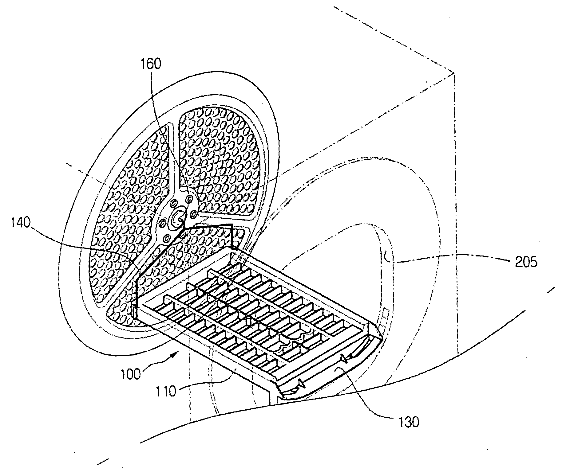
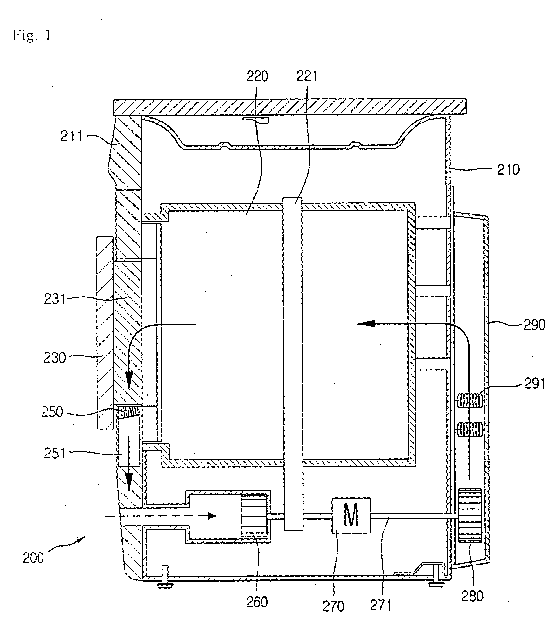
[0028]FIG. 1 is a sectional view of a condenser-type laundry dryer with a vibration / noise reduction device according to an embodiment of the present invention.

[0029] Referring to FIG. 1, a condenser-type laundry dryer 200 includes an outer case 210, a cylindrical drum 220 mounted in the outer case 210 to receive the laundry therein, a door 230 controlling the opening of the drum 220, and a belt 221 disposed around an outer circumference of the drum 220 to rotate the drum 220.

[0030] The condenser-type laundry dryer 200 further includes a motor shaft 271 connected to the belt 221 to transmit rotational force to the drum 220, a motor 270 for transmitting the rotational force to the motor shaft 271, and a co...


PUM


Abstract

There is provided a dry board received and fixed in a dry drum. The dry board is mounted in the dry drum and laundry such as shoes can be stably dried.

Description

BACKGROUND OF THE INVENTION [0001] 1. Field of the Invention [0002] The present invention relates to a laundry dryer, and more particularly, to a laundry dryer having a dry board on which tender clothes or shoes can be stably dried. [0003] 2. Description of the Related Art [0004] Generally, a drum-type laundry dryer is designed to perform the drying operation while rotating laundry loaded in a dry drum. The laundry rotates and drops by the rotation of the laundry drum. High-temperature dry air introduced into the dry drum is mixed with the laundry to vaporize the moisture soaked in the laundry. The laundry dryer may be classified into a condenser-type dryer and an exhaust-type dryer. The former is designed such that the air in the dry drum is directed to a condenser and a heater and is then returned to the dry drum. That is, the air circulates in the dryer without being exhausted out of the dryer. The latter is designed such that the air in the dry drum is directed to the condenser ...

Claims


Application Information

Patent Timeline
IPC IPC(8): D06F58/04D06F58/06
CPCD06F58/04
Inventor LEE, SOON JOPARK, SOO WON
Owner LG ELECTRONICS INC
Why Eureka
Try Eureka