Reflow device of ball screw

Inactive Publication Date: 2005-06-16
HIWIN TECH
View PDF4 Cites 13 Cited by
  • Summary
  • Abstract
  • Description
  • Claims
  • Application Information

AI Technical Summary

Benefits of technology

[0008] The primary object of the present invention is to provide a reflow device for ball screw which is able to reduce noise and vibration caused by the collision of rolling balls. To reduce the noise, it should start with the noise resource, the noise transmission and the sound-receiving surround. The noise problem can be permanently solved if the noise resource is reduced. Wherein by reducing the vibration of the noise resource can reduce the noise.
[0009] First of all, according to the kinetics of particles, when two objects collide with each other, the lower the coefficient of restitution “e” (general object is partial elastic member, 0<e<1), the greater the mechanical energy loss, therefore, the kinetic energy after collision will be reduced and the vibration of the objects will be reduced accordingly, so as to reduce the noise. The present invention is designed to improve the noise reduction by reducing the vibration of the noise-resource, thereby which uses materials with lower coefficient of restitution to collide with the rolling balls. Normally, soft material has lower coefficient of restitution than that of hard material. In this case, the reflow device in accordance with the present invention is designed as being a combinative structure made of hard material and soft material. Wherein turning portion of rolling path for turning moving direction of the rolling balls is covered with low coefficient of restitution material, Whereas the rest portion of the reflow device of the present invention is made of hard material. The hard material makes the rolling path strength enough to bear the high-speed moving rolling balls. When the rolling balls run through the reflow device and collide with the turning path, the kinetic energy of which will be substantially buffered and absorbed by the soft material. As a result, the kinetic energy reduction will cause vibration reduction, and so as to improve the noise reduction.
[0010] In addition, as shown in FIG. 4, which is a noise comparison diagram of illustrating the noises caused by striking of the rolling balls with collision portions made of different materials. Wherein material “A” is made of polyacetal material (which is the material commonly used in conventional reflow device), whereas material “B” is made of thermoplastic elastic material (the hardness is 35D-63D, tensile stress 10.3-41 MPa, Flexural modulus at normal atmospheric temperature 30 MPa-330 MPa). The diagram illustrates the noises caused by striking of the rolling balls with reflow device at different rotational speed. As can be seen in the diagram, the higher the rotational speed, the louder the noises caused by striking of material “A” and “B” with the reflow device. Sound is air pressure variation that can be received by ear. dB is used to measure sound level, the dB is defined as: dB=10 log (P / Po). Wherein “P” means actual sound pressure, “Po” is internationally acknowledged reference sound pressure. As can be seen from the above equation, the addition of sound is not arithmetic sum but sum of log. For example, when the sound pressure is doubled (P is doubled) the sound volume will be 3 dB louder, when the sound pressure is ten-fold higher, the sound volume will be 10 dB louder. As shown in FIG. 4, when the rolling balls are running at 2500 rpm, the noise caused by the thermoplastic elastic material is 3-4 dB lower than the noise caused by the polyacetal material. In other words, the sound pressure caused by the thermoplastic elastic material is half of the sound pressure caused by the polyacetal material. In this case, thermoplastic elastic material can be applied to covering the rolling path of the reflow device of the present invention, such that the vibration and noise reduction of it is hopefully much improved.

Problems solved by technology

However, the reflow device is right the noise source of the ball screw.
The noise problem of the conventional ball screw is generally caused by the two reasons as flows: first is because the reflow device 30 is normally made of a single material.

Method used


Image

  • Reflow device of ball screw
  • Reflow device of ball screw
  • Reflow device of ball screw

Examples


Embodiment Construction

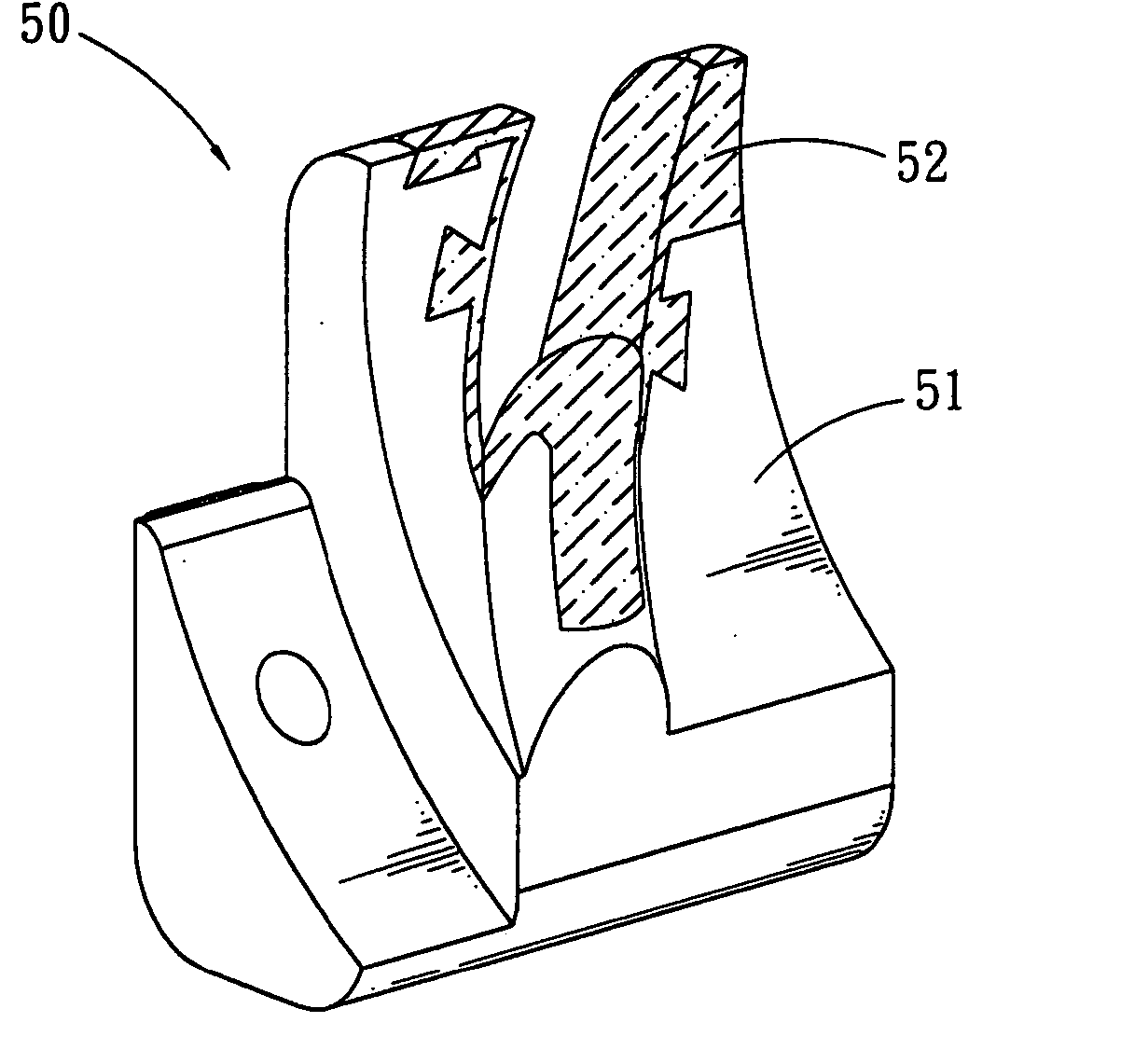
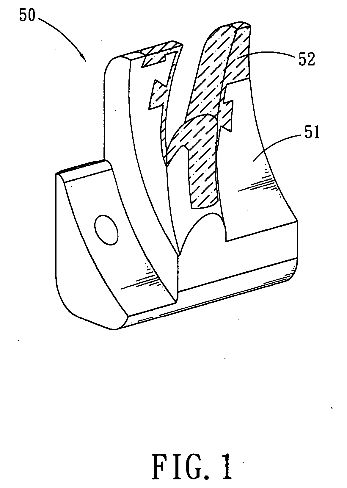
[0017]FIG. 1 is a partial perspective view of a reflow device for ball screw in accordance with an embodiment of the present invention. FIG. 2 is an illustrative view of showing the reflow device of FIG. 1 being collided by rolling balls. Here takes a reflow device equipped with end cup as an example, wherein the reflow device 50 is comprised of hard portion 51 and soft portion 52. Rolling balls 40 rolling in the reflow device 50 is surrounded by soft portion 52, the hard portion 51 covers the outside of the soft portion 52, so as to increase the strength of the reflow device 50. This structure ensures that the rolling balls 40, whatever entering the reflow device 50 from “A” side or “B” side, will collide with the soft portion 52. The collision of the rolling balls 40 can be substantially buffered and absorbed by the soft portion 52, such that the caused vibration and noise is effectively reduced.

[0018]FIG. 3 is a cross sectional view taken along C-C of FIG. 2. Wherein recirculati...


PUM


Abstract

The present invention relates to a reflow device of ball screw. The main characteristic of the reflow device is a combinative structure that is made up of the hard material and the soft material. And the soft material surround the balls when they are entered the reflow device, therefore can reduce the noise the balls bring on.

Description

BACKGROUND OF THE INVENTION [0001] 1. Field of the Invention [0002] The present invention relates to a reflow device for ball screw, and more particularly to a reflow device which is capable of improving the noise and vibration reduction during the operation of the ball screw. [0003] 2. Description of the Prior Arts [0004] Sound is caused by vibration of an object. Via the medium (such as gas, liquid or solid) vibration is able to transmit energy, and thus forms sound wave, all the sounds that can cause people's mental or physical unpleasing feeling are noises. [0005] The ball screw commonly applied in industrial circles generally includes shaft, screw nut assembly and rolling balls. The screw nut assembly is mounted on the shaft, whereas the rolling balls are disposed between the screw nut assembly and the shaft, such that the roll of the rolling balls produces relative movement between the shaft and the screw nut assembly. To enable the rolling balls to roll cyclically, it should ...

Claims


Application Information

Patent Timeline
IPC IPC(8): F16H25/22
CPCY10T74/19767F16H25/2219
Inventor YANG, PAULTSOU, CHIEN-WEI
Owner HIWIN TECH
Why Eureka
Try Eureka