Shell sand core machine

a shell sand core machine and shell technology, applied in the field of automatic core molding systems, can solve the problems of unacceptably variable casting quality, difficult removal of cured cores from the core box (matrix), and difficulty in retaining the proper shape of uncured cores, so as to minimize the premature curing of sand, function more reliably, and eliminate the resultant erratic machine movement

Inactive Publication Date: 2005-06-16
HAYES LEMMERZ INT
View PDF8 Cites 1 Cited by
  • Summary
  • Abstract
  • Description
  • Claims
  • Application Information

AI Technical Summary

Benefits of technology

[0010] These and other problems of the prior art are overcome in accordance with this invention by a core molding system that incorporates a separate sand fill station, a separate clamp, blow and cure station, and a separate cope eject and unload station. Specially designed equipment is used to remove unneeded core sand from the core cavity. In addition, external heat is applied to the hollowed out core to aid in curing the core. In accordance with one aspect of the invention, the core box (matrix) remains in a fixed vertical plane during the core formation and the clamping, blowing and curing stages. In accordance with another aspect of the invention, a special tooling mount on the clamp table, or pattern pins, move up and down in a vertical plane and eliminate the possibility of sand shift prior to curing of the sand with heat.
[0012] Advantageously, after the sand filled core has been blown in a shell-type or solid mold, and prior to being totally cured, a specially-designed sand removal device or vacuum manifold is introduced into the core box to remove any excess resin-coated sand, and to reclaim from the inside of the core any resin-coated sand that is not required before the sand in the core or mold is cured. Advantageously, this improves the quality and precision of the molds.
[0014] Furthermore, in one particular embodiment of the invention, the clamp, blow, and cure station is supplied with separate control air and blow air sources, including a reservoir of pressurized blow air, which avoids the compression of control air during the blow cycle and eliminates the resultant erratic machine movement during peak air demand. Also, the control air needs to be lubricated to allow for valves and cylinders to function more reliably; however, oil in the blow air would be a detriment to the core making process.
[0015] In accordance with another aspect of the invention, the core molding system is in a particular position and operation of the fill station and cure station, such that the reservoir of sand in the fill station is positioned with respect to the cure station to minimize premature curing of the sand prior to its introduction into the core box and the initiation of the curing process.
[0016] Another advantage of the core molding system in accordance with this invention is the use of a fixed core box for the forming and curing process. The single station utilized for both forming and curing the core eliminates movement of the core box after formation and before curing which frequently causes settling and shifting of the sand prior to curing in the prior art.

Problems solved by technology

A problem with the prior art is the difficulty in retaining the proper shape of the uncured core during the movement of the core box (matrix) prior to curing.
This results in cores of variable quality, and consequently results in castings of unacceptably variable quality.
The removal of the cured core from the core box (matrix) can be very difficult when the draft angle of the core box cavity is very small.
Should a portion of the cured core break off of the larger removed core and is retained in the core box it will be very troublesome.
The cured core is hard and could be difficult to remove.
The use of any sharp tools or excessive force can mar or damage the core box (matrix) which will acerbate the condition and subsequently made cores might not be drawn (removed) easily.
Another problem with the prior art is that the sand fill station is not sufficiently isolated from the cure station.
The resin coated core sand that is used in producing the shell cores is very special and expensive.
Consequently, heat from the cure station may initiate the curing process in the sand while it is stored in the fill station prior to blowing into the core box, whereby the sand in the fill station becomes partially or fully hardened before it is introduced into the core box and is unable to produce a core in the desired consistency and casting shape.
Another problem with a hollow core, the sand in the inside is not totally cured and the grains of sand have little or no strength and are not bonded together.
This can result in quality problems during subsequent manufacturing operations.
A problem with the prior art is that, if a single source of air is utilized to provide both “control air” and “blow air,” erratic machine movement can result from the decompression of the control air during the blowing process, which results in cores of variable quality.

Method used


Image

  • Shell sand core machine
  • Shell sand core machine
  • Shell sand core machine

Examples


Embodiment Construction

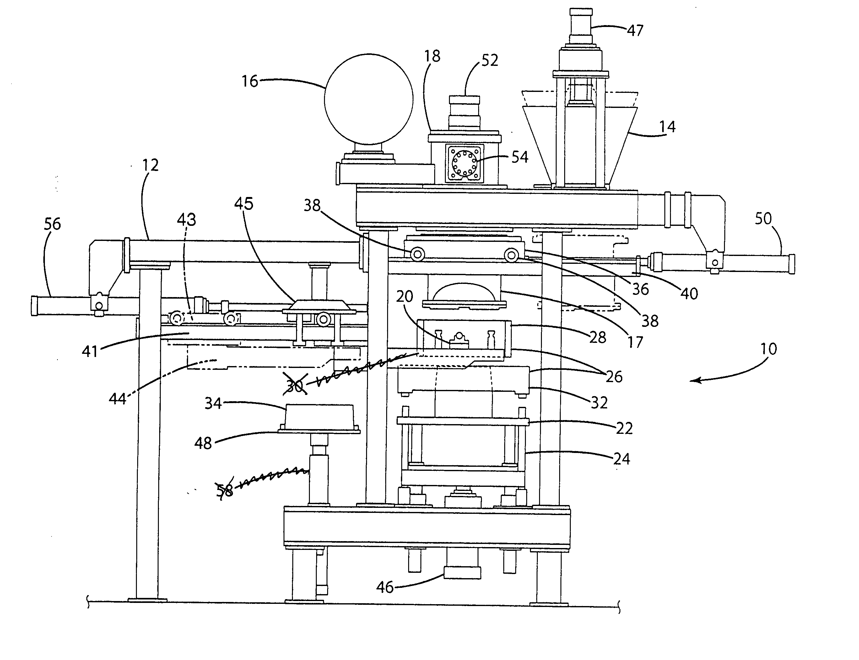
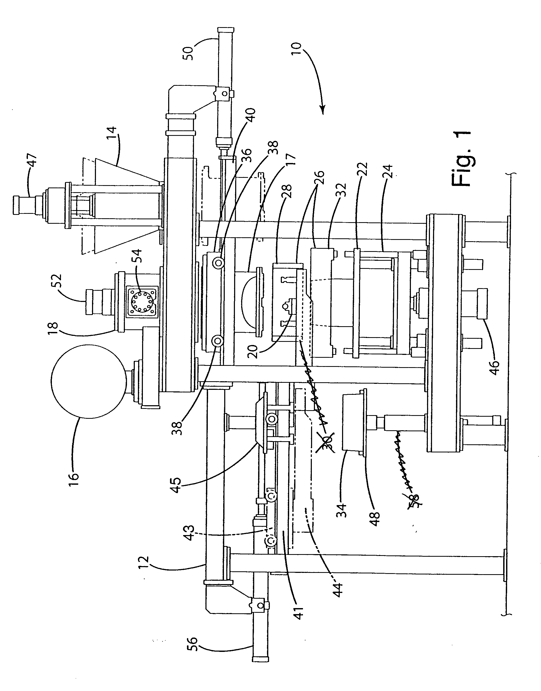
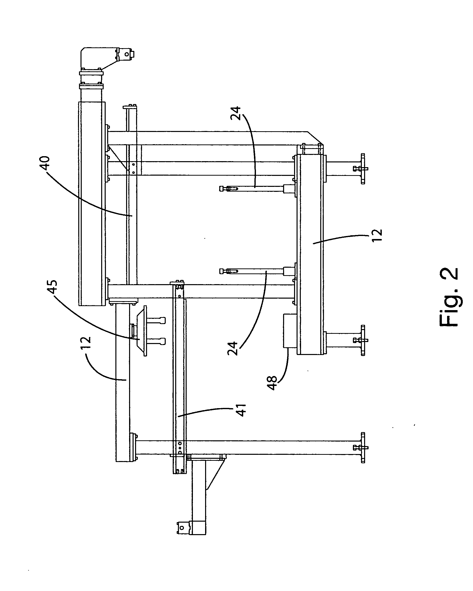
[0027] Depicted in FIG. 1 is a frontal view of the core molding machine 10 incorporating a heavy machine frame assembly 12 (FIG. 2) which supports a sand hopper 14, an air reservoir 16, and a blow head 17. A clamp table 22 and pattern pins 24 support a core box (matrix) 26 which consists of a cope 28 resting on a trunnion system 20 that is compressed against the drag 32 to form a core 34. The core box (matrix) 26 is brought adjacent to a sand chamber transfer car 36.

[0028] As shown in FIG. 1, the blow head / sand magazine 17 and sand chamber transfer car 36 are aligned with the sand hopper 14 in a position to receive the sand. Sand is introduced from the sand hopper 14 to the blow head / sand magazine 17 through the operation of the sand hopper cylinder 47 which opens and closes a valve in the sand hopper 14 which releases the sand by gravity when the sand hopper cylinder 47 is extended. The sand hopper 14 is closed by retraction of the sand hopper cylinder 47 after the sand has been i...


PUM

PropertyMeasurementUnit
pressureaaaaaaaaaa
heataaaaaaaaaa
shapeaaaaaaaaaa

Abstract

An automated core molding machine, including a method and apparatus for blowing and curing of cores wherein the special core box remains in a fixed vertical plane during the core forming and curing stages.

Description

BACKGROUND OF THE INVENTION [0001] 1. Field of the Invention [0002] The invention relates to automated core molding systems and, more particularly, to a method and apparatus for the blowing and curing of cores wherein the special core box (matrix) remains in a fixed vertical plane during core formation and curing. [0003] 2. Description of Related Art [0004] Metal castings are typically produced by the introduction of molten metal into a mold in the form of the casting, also termed a “core,” typically utilizing sand as the core material. As an initial step in the process, the core must be formed and cured. This occurs in a core box (matrix). The forming of the core is termed “blowing,” and involves the introduction of resin coated sand into a core box (matrix) to produce a core in the desired casting shape. A problem with the prior art is the difficulty in retaining the proper shape of the uncured core during the movement of the core box (matrix) prior to curing. This results in core...

Claims


Application Information

Patent Timeline
Patent Type & Authority Applications(United States)
IPC IPC(8): B22C15/24
CPCB22C15/24
Inventor MCKIBBEN, KENNETH D.GOULD, ALANMINOR, DANIEL D.
Owner HAYES LEMMERZ INT
Why Eureka
Try Eureka