Lock mechanism for a sliding sleeve

Active Publication Date: 2005-06-16
BAKER HUGHES INC
View PDF25 Cites 52 Cited by
  • Summary
  • Abstract
  • Description
  • Claims
  • Application Information

AI Technical Summary

Benefits of technology

[0007] A locking device prevents stressing of other components used to hold tool portions against relative movement until a desired location is reached. A locking dog holds a first component, such as a sliding sleeve to a second component, such as a mandrel until pressure can move a piston and remove support for the dog. The same pressure that removes support

Problems solved by technology

While in many situations such arrangements work reasonably well, there can be situations during run in that could trigger a premature failure of the shear locking mechanism.
Such early and unintended release of a shear retainer could have the result of an inability to set the tool or operate the tool where needed.
It has been learned that in some applications, the process of running a tool into the desired location can put cyclical stresses on shear pins so as to cause them

Method used


Image

  • Lock mechanism for a sliding sleeve
  • Lock mechanism for a sliding sleeve
  • Lock mechanism for a sliding sleeve

Examples


Embodiment Construction

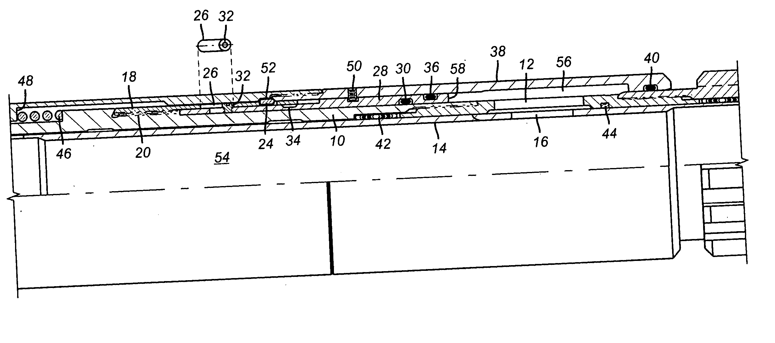
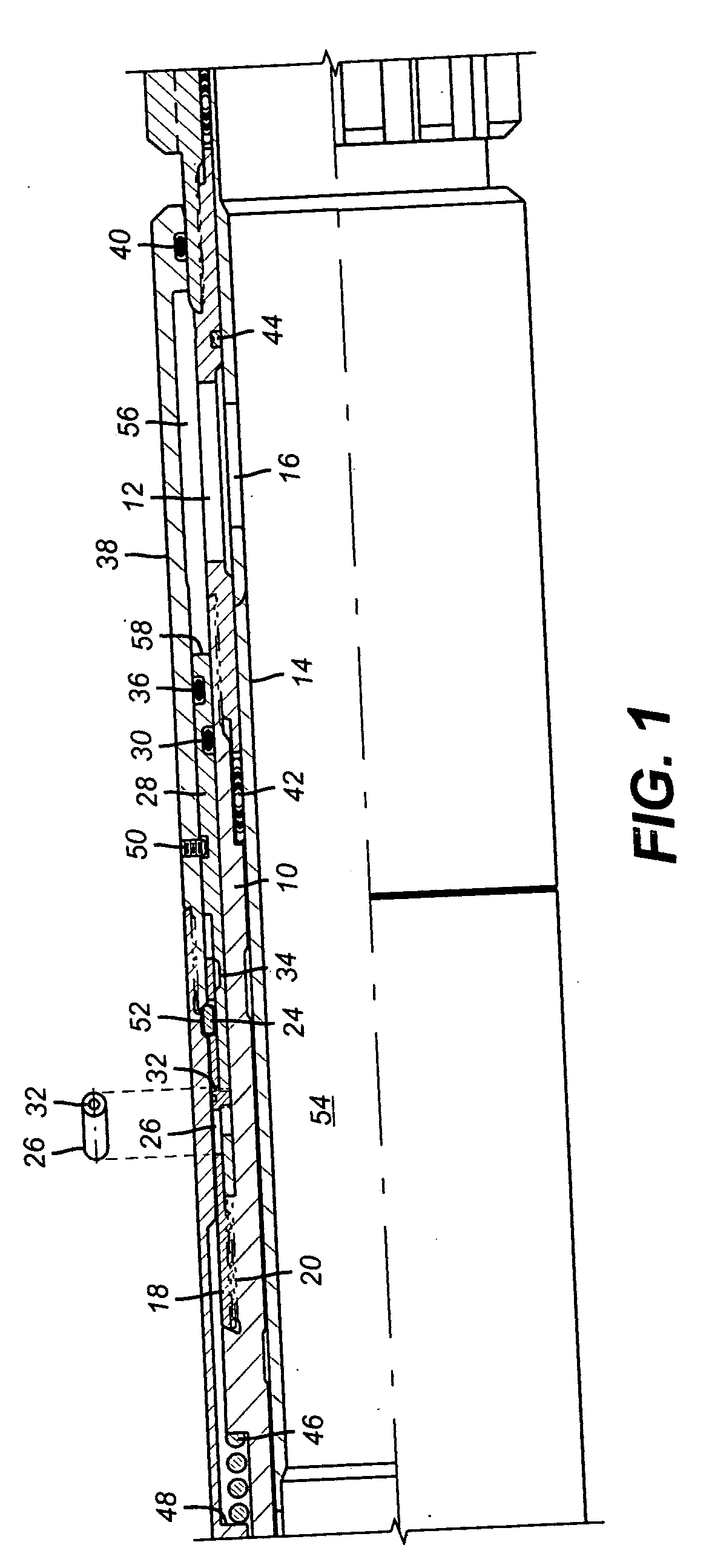
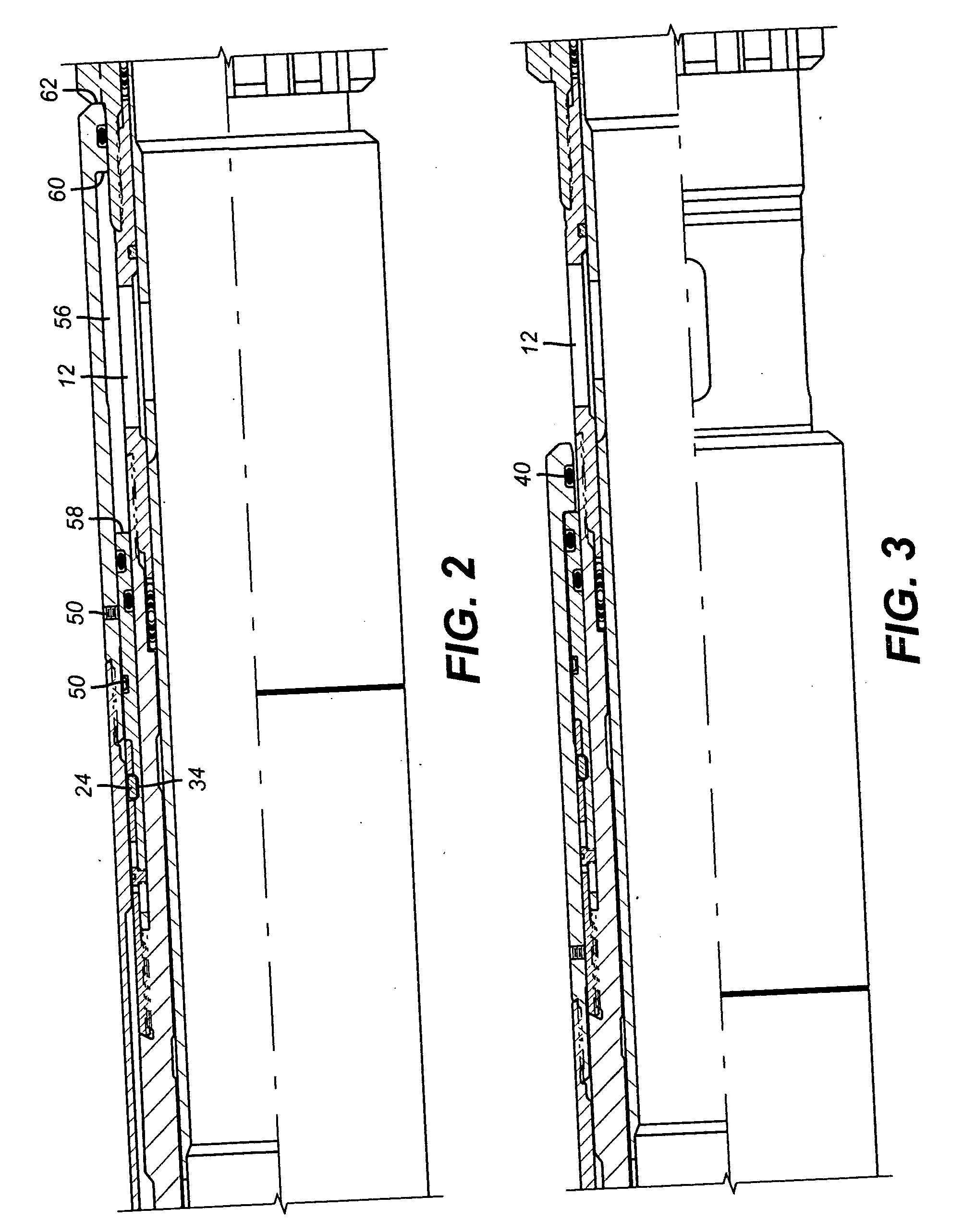
[0014] The preferred embodiment will be illustrated in the context of a tool that includes a pressure set packer in combination with a sliding sleeve assembly. As seen in FIG. 1, the mandrel 10 has a port 12. Mandrel 10 can be mounted below the packer, which is not shown. An internal sleeve 14 has a port 16 that is in alignment with port 12 of mandrel 10 for run in. A dog retainer 18 is secured to mandrel 10 at thread 20. Dog retainer 18 has a window 22 in which sits a dog 24. Those skilled in the art will appreciate that alternatives to the dog 24 could be employed, such a collets or a c-ring, to name a few examples. Dog retainer 18 has a second window 26. Piston 28 is mounted over mandrel 10 with seal 30 in between. A screw 32 is attached to piston 28 and extends into window 26 of the dog retainer 18. Piston 28 has a groove 34 that allows the dog 24 to become unsupported when the groove 34 is brought into alignment with it, as will be explained below. Piston 28 also has a seal 36 ...


PUM


Abstract

A locking device prevents stressing of other components used to hold tool portions against relative movement until a desired location is reached. A locking dog holds a first component, such as a sliding sleeve to a second component, such as a mandrel until pressure can move a piston and remove support for the dog. The same pressure that removes support for the dog to unlock the lock also forces a retainer, such as a shear pin that holds a sleeve to break to allow the sleeve to shift. The locking dog keeps stress off the shear pin when the locking dog is supported in the run in configuration. An alternative design uses a grease filled cavity to dampen shocks that could load a shear pin to the point of failure.

Description

PRIORITY INFORMATION [0001] This application claims the benefit of U.S. Provisional Application No. 60 / 528,688, filed on Dec. 11, 2003.FIELD OF THE INVENTION [0002] The field of this invention is lock devices that selectively prevent relative movement between two downhole components until a predetermined condition is met and the device is defeated to allow relative movement. BACKGROUND OF THE INVENTION [0003] Many downhole applications require adjacent components to remain in a fixed relationship during run in. In many cases, shear pins or other temporary restraints are employed to break away under an applied force. While in many situations such arrangements work reasonably well, there can be situations during run in that could trigger a premature failure of the shear locking mechanism. Such early and unintended release of a shear retainer could have the result of an inability to set the tool or operate the tool where needed. It has been learned that in some applications, the proces...

Claims


Application Information

Patent Timeline
IPC IPC(8): E21B23/04E21B23/06E21B34/00E21B34/10
CPCE21B34/103E21B34/102
Inventor GOMEZ, ALFREDO
Owner BAKER HUGHES INC
Why Eureka
Try Eureka