LED package

a technology of led packaging and led ring, which is applied in the direction of basic electric elements, electrical apparatus, and semiconductor devices, can solve the problems of inability to meet the foregoing requirements of the common optical mouse sold in the market, dark fringe problems, and serious light loss, and achieves uniform and highly efficient light focusing functions. , the effect of better gray scale contrast effect and better calculation of distance and direction of mouse displacemen

Inactive Publication Date: 2005-06-16
LEAHSIN TECH +1
View PDF1 Cites 8 Cited by
  • Summary
  • Abstract
  • Description
  • Claims
  • Application Information

AI Technical Summary

Benefits of technology

[0007] The primary object of the invention is to provide an improved LED package, which comprises a stand, an LED chip, and an epoxy packaging object, wherein a bowl section for accommodating the LED chip is disposed on the stand, and the present invention improves the prior-art LED package to allow the illuminating light emitted from the LED to travel in the same direction, and thus achieving the uniform and highly efficient light focusing function. As a result, the optical mouse can capture an image with a better gray scale contrast effect, and let the image sensing processor compute the distance and direction of the mouse

Problems solved by technology

However, the common optical mouse sold in the market is unable to meet the foregoing requirements, and a darker fringe is usually formed around the bright section mainly because of the traditional LED.
Further, since the anode in the middle of the LED chip is used for connecting to the power supply and does not have the illuminating function, which will cause a darker fringe problem (as shown in FIG. 6).
However, since there are discrepancies in the design and common errors caused in the packaging process, which will cause a serious loss of light, therefore, only a small improvement can be made.
The image sensing processor cannot accurately compute the distance and direction of the mouse's displacement, more particularly when the desktop is smooth.
Plastic Materials are adopted in the optical process for lowering the production co

Method used


Image

  • LED package
  • LED package
  • LED package

Examples


Embodiment Construction

[0024] The objects, spirits and advantages of the preferred embodiments of the present invention will be readily understood by the accompanying drawings and detailed descriptions, wherein:

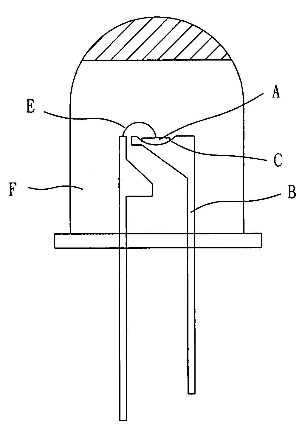
[0025] Please refer to FIGS. 12A and 12B for the front view and top view of the present invention respectively. The improved LED package disclosed in this invention comprises a first stand 1, a second stand 2, an LED chip 3, and an epoxy packaging object 4, wherein the first stand 1 has a concave bowl section 11; a pin 12 is extended from the bottom of the bowl section 11; the second stand 2 is disposed adjacent to the first stand 1 but keeps a certain distance from the first stand 1; a second pin 21 is disposed at the bottom of the second stand 2; the LED chip is disposed in the bowl section 11 at the top of the first stand 1; the anode of the LED chip 3 uses a conductive metal wire 5 is electrically connected to the second stand 5; the epoxy packaging object 4 contains the foregoing first stand ...


PUM


Abstract

An improved LED package comprises a first stand, a second stand, an LED chip, an epoxy packaging object, wherein the first stand further comprises a concave bowl section, and a first pin is extended from the bottom of the first stand, and a second stand is disposed adjacent to the first stand and keeps a certain distance from the first stand. The LED chip is disposed in the bowl section at the top of the first stand, and the anode of the LED chip makes use of a conductive metal wire to electrically connect the second stand. The epoxy packaging object encapsulates the first stand, second stand, and LED chip inside and just leaves the first and second pins exposed. A plane perpendicular to the optical path of the light emitted by the LED chip is disposed on the top surface of the packaging object, and the top surface has more than one circular protrusion to achieve the objective of enhancing the brightness and uniformity of luminescence.

Description

1. FIELD OF THE INVENTION [0001] The present invention relates to an improved LED package, more particularly to a package having a top plane perpendicular to the optical path and at least one circular protrusion disposed thereon. 2. BACKGROUND OF THE INVENTION [0002] In compliance with the fast pace and rapid change in the development of science and technology, all kinds of high-tech products are developed and introduced constantly, not only improving the quality of our life, but also bringing us lots of convenience. Taking the digital image processing for example, a digital array is generally used in the digital image processing for representing a physical image (as shown in FIG. 1). In this regard, a physical image is generally being divided into small regions called “picture elements” or “pixels” for short. The most common subdivision scheme is the rectangular sampling grid shown in the figure, where the image is divided into horizontal lines composed of adjacent pixels. The loca...

Claims


Application Information

Patent Timeline
IPC IPC(8): H01L33/54
CPCH01L33/54H01L2224/48091H01L2224/48247H01L2924/181H01L2924/00012H01L2924/00014
Inventor LIN, TIMOTHYLIN, CHENG-I
Owner LEAHSIN TECH
Why Eureka
Try Eureka