Outer rotor type motor for drum type washing machine and method for fabricating the same

a drum type, outer rotor technology, applied in the direction of washing machine with receptacles, magnetic circuit rotating parts, magnetic circuit shapes/forms/construction, etc., can solve the problems of complicated fabrication process, high noise, and high energy loss, so as to prolong the life of the motor, improve reliability, and cut off the reaction of the surface

Active Publication Date: 2005-06-16
LG ELECTRONICS INC
View PDF9 Cites 39 Cited by
  • Summary
  • Abstract
  • Description
  • Claims
  • Application Information

AI Technical Summary

Benefits of technology

[0034] An object of the present invention is to provide an outer rotor type BLDC motor for a drum type washing machine, which has a stator that can reduce material and weight required for fabrication, has a simple fabrication process, and can be mounted on a fixed side, such as a tub or a bearing housing securely.
[0036] Another object of the present invention is to provide an outer rotor type BLDC motor for a drum type washing machine, which can prevent scratch on a surface of the steel plate outer rotor from occurring effectively, and cut off reaction of the surface with detergent effectively, for extending a lifetime of the motor, and improving reliability.
[0037] A further object of the present invention is to provide an outer rotor type BLDC motor for a drum type washing machine, which can enhance a rigidity of the outer rotor, solve the problem of throbbing and consequential noise.
[0039] To achieve these objects and other advantages and in accordance with the purpose of the invention, as embodied and broadly described herein, an outer rotor type motor for a drum type washing machine includes an annular stator core having multiple layers formed by winding a base portion in a shape of stripe with Ts projected from the base portion in a helix starting from a bottom layer to a top layer, an insulator insert molded to cover an outside surface of the stator core for insulating the stator core electrically, and fastening portions formed as one body with the insulator each projected from an inside circumferential surface of the stator core toward a center of the stator, for fixedly securing the stator to the tub, wherein the base portion of the stator core has an arc shaped slots each for reducing stress in winding the core as well as serving as a portion of a fastening hole, and each of the fastening portion of the insulator formed to cover the slots has a fastening hole formed therein.

Problems solved by technology

The type in which the driving power of the motor is transmitted to the drum, not directly, but indirectly through the motor pulley and the drum pulley, has much energy loss in the course of power transmission, and causes much noise in the course of power transmission.
However, the method for fabricating the stator 6 by means of the divisional cores DC has, not only a complicate fabrication process, but also loss of much material.
Therefore, even if a helical type core HC is favorable, in which a sheet of steel plate having the Ts 151 and the base portions 150 is stacked turning in a helix for reducing the material loss, and making the fabrication process simple, since it is required to bend the sheet of metal punched out in a shape of a stripe into the helix, the helical core has a drawback in that the projected portion for fastening the stator to the tub can not be formed on an inner side of the core.
However, the related art steel plate rotor R has the following problems.
Despite of anti-rusting heat treatment of a surface of the related art steel plate rotor R, rust occurs on a portion of the surface scratched during transportation or other situations.
The surface of the rotor also corrodes due to chemical reaction of detergent stuck to the surface of the rotor as the drum type washing machine is used for a long time.
In the meantime, during the spinning for water extraction, the sidewall 120 of the related art steel plate rotor 100 throbs intensely due to electromagnetic interaction (attraction and repulsion) with the stator, leading to increase noise.

Method used


Image

  • Outer rotor type motor for drum type washing machine and method for fabricating the same
  • Outer rotor type motor for drum type washing machine and method for fabricating the same
  • Outer rotor type motor for drum type washing machine and method for fabricating the same

Examples


first embodiment

[0078] the present invention will be described.

[0079]FIG. 7 illustrates a perspective view of an exterior of the stator in accordance with a first preferred embodiment of the present invention, FIG. 8 illustrates a perspective view of the core in the stator in FIG. 7, FIG. 9 illustrates a plan view of key portions of FIG. 7, and FIG. 10 illustrates a cross sectional view of FIG. 9, showing an inside of a fastening portion for reference.

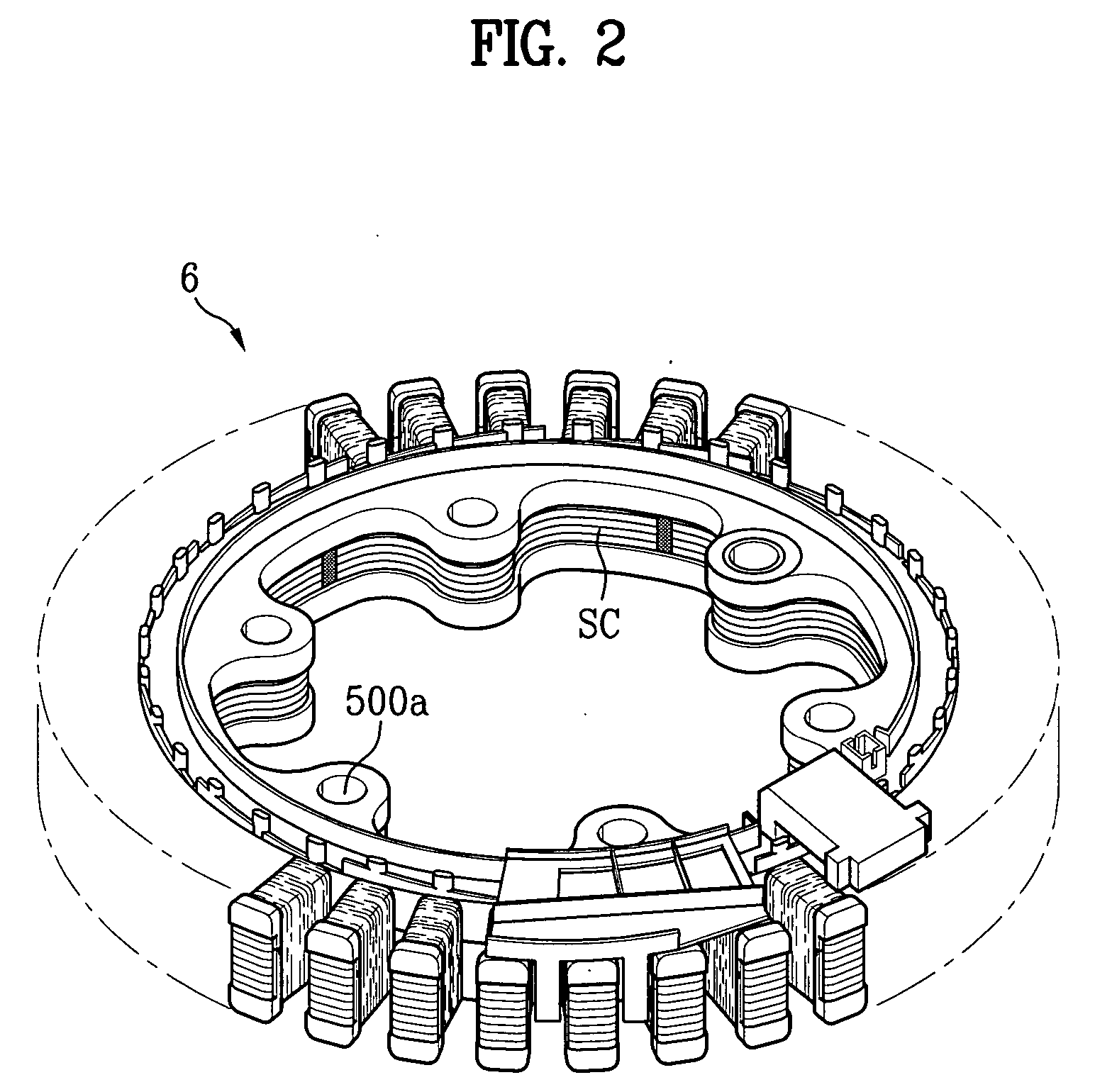
[0080] The stator 6 of a direct coupling type motor in accordance with a first preferred embodiment of the present invention includes an annular stator core 15 having multiple layers formed by winding a steel plate with Ts 151 and base portion 150 in a helix starting from a bottom layer to a top layer such that a layer overlaps with the next layer, an insulator 144 insert molded to cover an outside surface of the stator core for insulating the stator core electrically, and three or more fastening portions 143 formed as one body with the insulator 144...

second embodiment

[0125] The work of the second embodiment stator will be described.

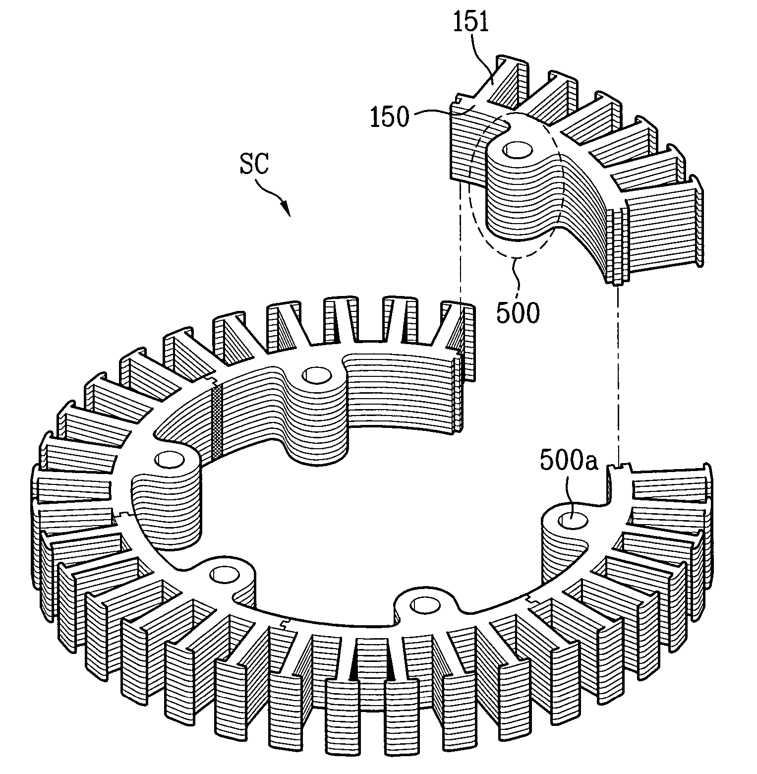
[0126] Different form the divisional core DC, the application of so called helical core HC, formed by stacking a steel plate having Ts 151 and a base portion 150 while winding in a helix, to the embodiment as the stator core 15 also permits the embodiment to omit steps of aligning, and welding the core segments, to simplify a fabrication process.

[0127] Moreover, different from the divisional core, since the stator core 15 has no projected portion, the stator core 15 permits to reduce waste of material.

[0128] That is, a method for fabricating a stator of the embodiment not only simplifies a fabrication process, but also reduces waste of material.

[0129] Moreover, even if the stator 6 of the embodiment improves structures of the upper, and the lower insulator 60a, and 60b such that no projected portions are formed at the core itself for supporting the fastening force at the time of fastening the stator 6 to the tub si...

third embodiment

[0144] A third embodiment stator core will be described with reference to FIGS. 20˜26.

[0145]FIG. 20 illustrates a perspective view of an exterior of a stator in accordance with a third preferred embodiment of the present invention, FIG. 21 illustrates a disassembled perspective view of FIG. 20, FIG. 22 illustrates a plan view of an upper insulator, and FIG. 23 illustrates a plan view of a lower insulator.

[0146]FIG. 24 illustrates a perspective view of a bottom of a portion of the upper insulator in FIG. 21, FIG. 25 illustrates a section of a fastening portion across a line II-II in. FIG. 21, and FIG. 26 illustrates a perspective view of a supporter of a metal ring shape applicable to the stator in FIG. 20.

[0147] Referring to FIGS. 20˜26, the stator 6 of an outer rotor type motor in accordance with a third preferred embodiment of the present invention includes an annular stator core 15 having multiple layers formed by winding a steel plate with a stripe shape of base portion 150 an...


PUM

PropertyMeasurementUnit
thicknessaaaaaaaaaa
weightaaaaaaaaaa
stressaaaaaaaaaa

Abstract

Direct coupling type motor for drum type washing machine having a stator which can reduce material required for fabrication, and a weight after fabrication, simplify a fabrication process, and can be mounted on a fixing side, such as a tub or a bearing housing securely, and a rotor which can enhance rigidity an outer rotor and protect a surface of the outer rotor.

Description

CROSS-REFERENCE TO RELATED APPLICATIONS [0001] This application claims the benefit of Korean Application Nos. P2003-0089721, 0089722, 0089723, 0089724, and 0089726 all of which were filed on Dec. 10, 2003, and are hereby incorporated by reference as if fully set forth herein. BACKGROUND OF THE INVENTION [0002] 1. Field of the Invention [0003] The present invention relates to drum type washing machines, and more particularly, to an outer rotor type BLDC motor applicable to a direct coupling type drum type washing machine, and a method for fabricating the same. [0004] 2. Discussion of the Related Art [0005] In general, a drum type washing machine washes laundry by using a friction force between a drum rotated by a driving power of a motor and laundry in a state detergent, washing water, and the laundry are introduced into the drum, shows almost no damage to, and entangling of the laundry, and has pounding, and rubbing washing effects. [0006] In the related art drum type washing machin...

Claims


Application Information

Patent Timeline
Patent Type & Authority Applications(United States)
IPC IPC(8): D06F37/22D06F37/30H02K1/14H02K1/18H02K1/22H02K1/27H02K3/52H02K7/14H02K15/02
CPCD06F37/304H02K1/148Y10T29/49012H02K3/522H02K1/187
Inventor LEE, DEUG HEECHOI, SEUNG BONGAHN, BYUNG HWAN
Owner LG ELECTRONICS INC
Why Eureka
Try Eureka