Light emitting device and method of manufacturing the same

Active Publication Date: 2005-06-16
NICHIA CORP
View PDF6 Cites 87 Cited by
  • Summary
  • Abstract
  • Description
  • Claims
  • Application Information

AI Technical Summary

Benefits of technology

[0041] With this method, a light emitting device capable of emitting light of various color hues with an excellent color mixing property can be manufactured.
[0042] The method for manufacturing a light emitting device may comprise the steps of injecting a transparent resin into each recess of the package and curing the transpare

Problems solved by technology

Therefore, it is impossible to obtain a mixed color li

Method used


Image

  • Light emitting device and method of manufacturing the same
  • Light emitting device and method of manufacturing the same
  • Light emitting device and method of manufacturing the same

Examples


embodiment 1

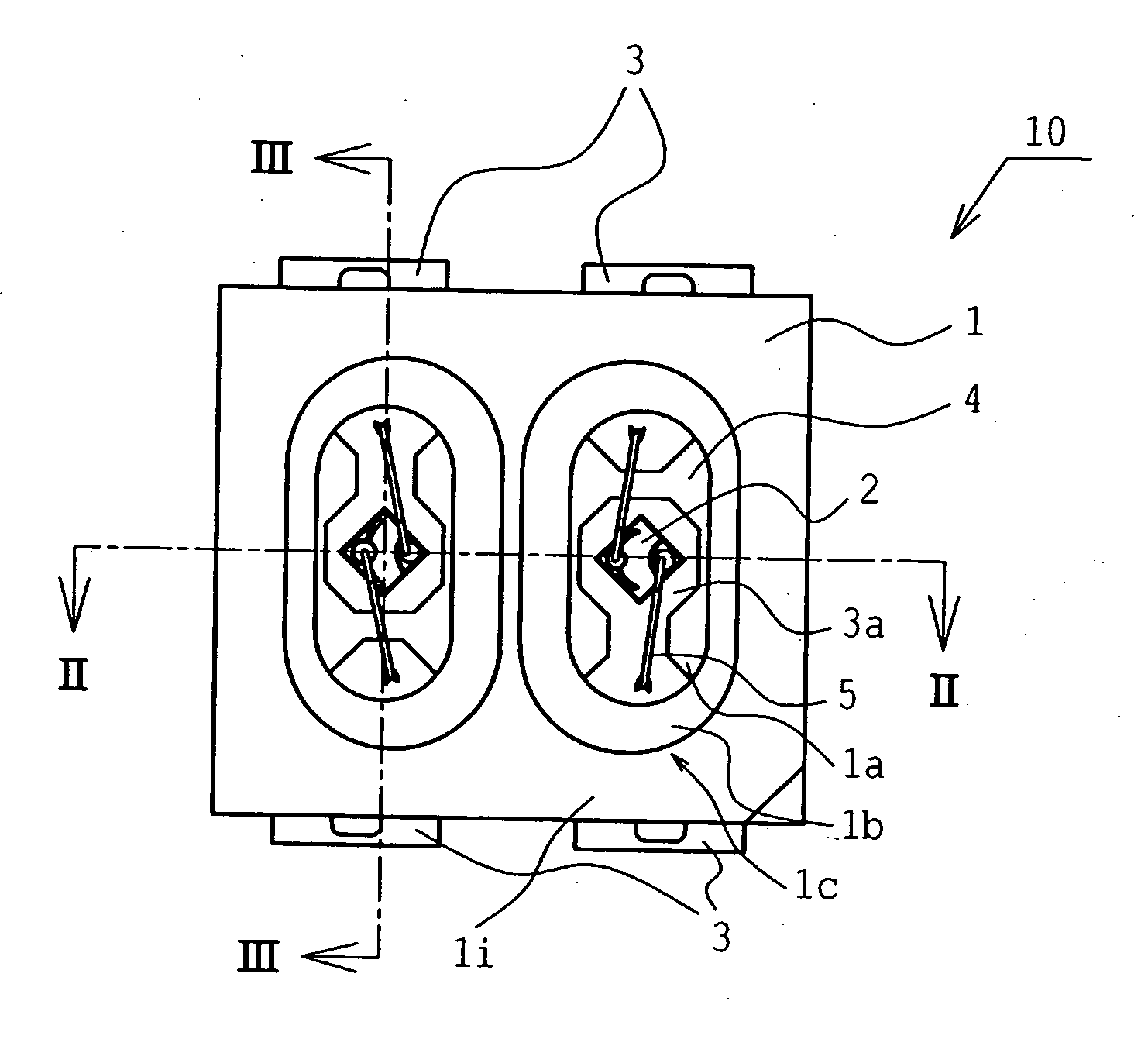
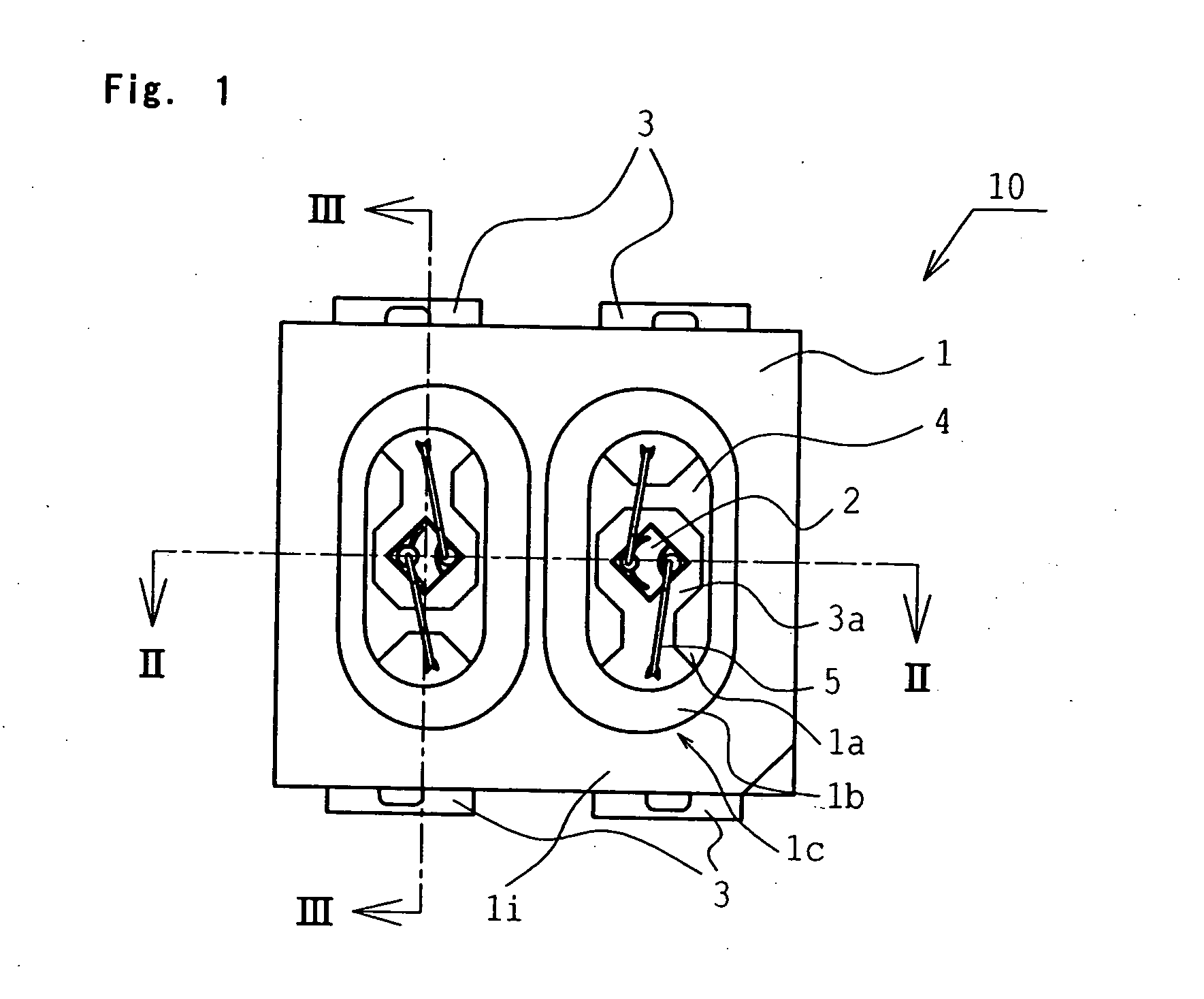
[0066]FIG. 1 is a schematic plan view showing a light emitting device according to the first embodiment. FIG. 2 shows a cross-sectional view taken along line II-II of a light emitting device according to the first embodiment of the present invention. FIG. 3 shows a cross-sectional view taken along line III-III of a light emitting device according to the first embodiment of the present invention. FIG. 4 is a schematic perspective view showing a rear side of a light emitting device according to the first embodiment of the present invention.

(Light Emitting Device)

[0067] The light emitting device 10 according to the first embodiment comprises a light emitting element 2 and a package 1 formed with two recesses each having a bottom surface 1a for mounting the light emitting element 2 and a side surface 1b extending from the bottom surface 1a. An electrode 3 is disposed on the bottom surface 1a of the recess 1c of the package 1, and the light emitting element 2 is mounted on the mountin...

embodiment 2

[0090]FIG. 5 is a schematic plan view showing a light emitting device according to Embodiment 2. FIG. 6 is a schematic cross-sectional view taken along line VI-VI in FIG. 5, showing the light emitting device according to Embodiment 2. A light emitting device according to Embodiment 2 will be described below, except for the construction and elements similar to Embodiment 1. As used herein, the various embodiments are described in the drawings according to the following explanation: the number used in the ten's (10) digit location is related to the number of the embodiment and the one's (1) digit location is used to indicate the same elements as described in connection with Embodiment 1.

[0091] The light emitting device 20 according to Embodiment 2 has a similar construction as the light emitting device 10 according to Embodiment 1, except for the configuration defining the recess 21c.

[0092] The top edge of the recess 21c of the package 21 is formed in the shape of a rectangle. It is...

embodiment 3

[0093]FIG. 7 is a schematic plan view showing a light emitting device according to Embodiment 3. FIG. 8 is a schematic cross-sectional view taken along line VIII-VIII of FIG. 7, showing the light emitting device according to Embodiment 3. A light emitting device according to Embodiment 3 will be described below, except for the construction similar to that in Embodiment 1. A light emitting device according to Embodiment 3 will be described below, except for the construction similar in Embodiment 1.

[0094] The light emitting device 30 according to Embodiment 3 has a similar construction as the light emitting device 10 according to Embodiment 1, except for the number and the size of the recesses 31c.

[0095] Three recesses 31c are formed in the package 31. Each recess is defined by a bottom surface 31a and a side surface 31b with the opening of the recess being wider than the bottom thereof. A recess 31c has, in a vertical cross section, a first angle 31p between the top surface 31i and...


PUM


Abstract

A light emitting device capable of emitting an excellent mixed color light, and a light emitting device capable of enhancing the concentration of mixed light or the directivity of emission is provided. The light emitting device comprises a light emitting element and a package. The package includes at least two recesses each having a bottom surface for mounting a light emitting element thereon and a side surface extending from the bottom surface, wherein each recess has, in a vertical cross section of the recess, a vertical line passing through the center of the bottom surface of the recess which is different than a vertical line passing through the intersection of a first straight line extending along an inclined edge of the recess and a second straight line extending along an inclined edge on another side of the recess.

Description

BACKGROUND OF THE INVENTION [0001] 1. Field of the Invention [0002] The present invention relates to a light emitting device and a package for a light emitting device, which is used for a lighting apparatus, a display, a backlight of a portable telephone, a flash for cameras, an auxiliary light for time-varying image illumination and the like, and to a manufacturing method thereof. [0003] 2. Discussion of the Related Art [0004] A light emitting device using a light emitting element is compact and emits light of a clear color with good power efficiency. It is also free from trouble such as a burn-out, because the light emitting element is a semiconductor element. Moreover, a light emitting element has an excellent initial drive characteristic, high vibration resistance and durability to endure repetitive ON / OFF operations. Due to such excellent properties, a light emitting device using a light emitting element such as a light emitting diode (LED) or a laser diode (LD) has been used a...

Claims


Application Information

Patent Timeline
IPC IPC(8): H01J1/62H01L25/075H01L33/54H01L33/56H01L33/62
CPCH01L25/0753H01L33/60H01L2224/32245H01L2224/48247H01L2224/48465H01L2224/73265H01L2224/48257H01L2924/00H01L2924/00012H01L2924/181H01L2224/48091H01L2924/00014
Inventor SUMITANI, NAOFUMI
Owner NICHIA CORP
Why Eureka
Try Eureka