RFID system with an adaptive array antenna

a technology of adaptive array and rfid system, which is applied in the direction of electrical signalling details, burglar alarm mechanical actuation, instruments, etc., can solve the problems of limited range operation of conventional rfid system, achieve the effect of increasing the operating range of the rfid system, maximizing and increasing the received signal-to-noise ratio

Inactive Publication Date: 2005-06-16
RENDA TRUST
View PDF7 Cites 34 Cited by
  • Summary
  • Abstract
  • Description
  • Claims
  • Application Information

AI Technical Summary

Benefits of technology

[0007] The present invention relates to use of a smart antenna for a RF reader on a Radio Frequency Identification (RFID) system to significantly increase the operating range of the RFID system. The smart antenna can be an adaptive antenna array. The smart antenna comprises a plurality of antenna elements and, by combining the signals from multiple antenna elements, significantly increases the received signal-to-noise ratio. In a noise limited environment, combining the signals to maximize the received signal-to-noise ratio can be based on the maximal ratio combining (MRC) principle. To achieve the best signal quality, the received signal from each antenna can be phase-shifted such that the resultant signals from all antennas are in phase. In addition, the signal from each antenna can be scaled in amplitude based on the square root of its received signal-to-noise ratio.

Problems solved by technology

Conventional RFID systems are limited to short range operation because of limited transmission power available on the return link from the RF tag to the RF reader.

Method used


Image

  • RFID system with an adaptive array antenna
  • RFID system with an adaptive array antenna
  • RFID system with an adaptive array antenna

Examples


Embodiment Construction

[0013] Reference will now be made in greater detail to a preferred embodiment of the invention, an example of which is illustrated in the accompanying drawings. Wherever possible, the same reference numerals will be used throughout the drawings and the description to refer to the same or like parts.

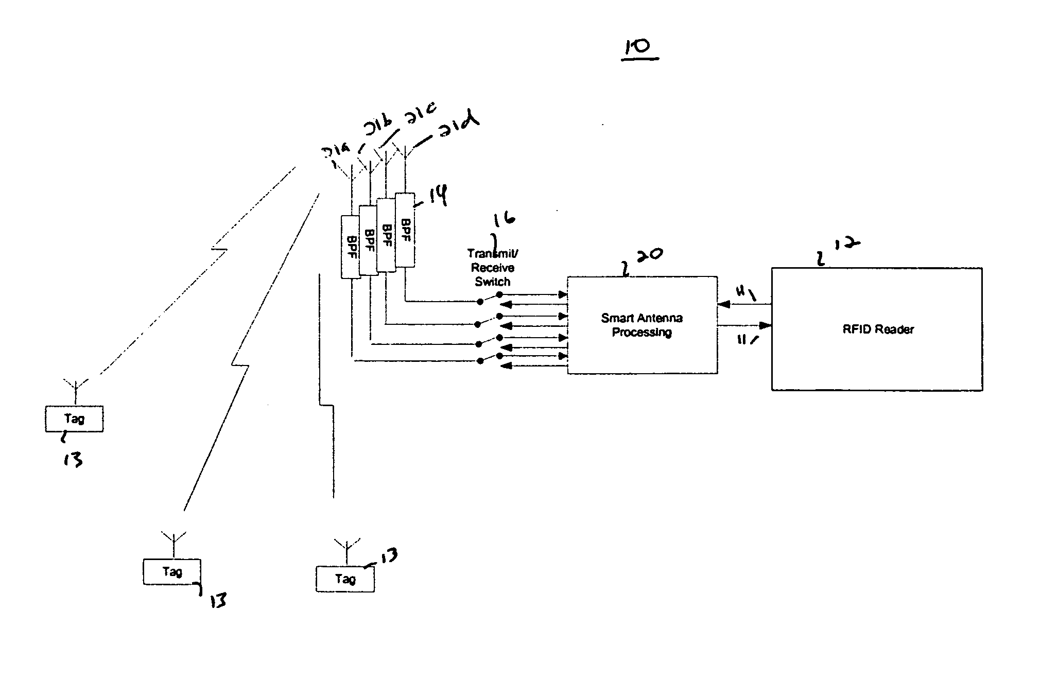
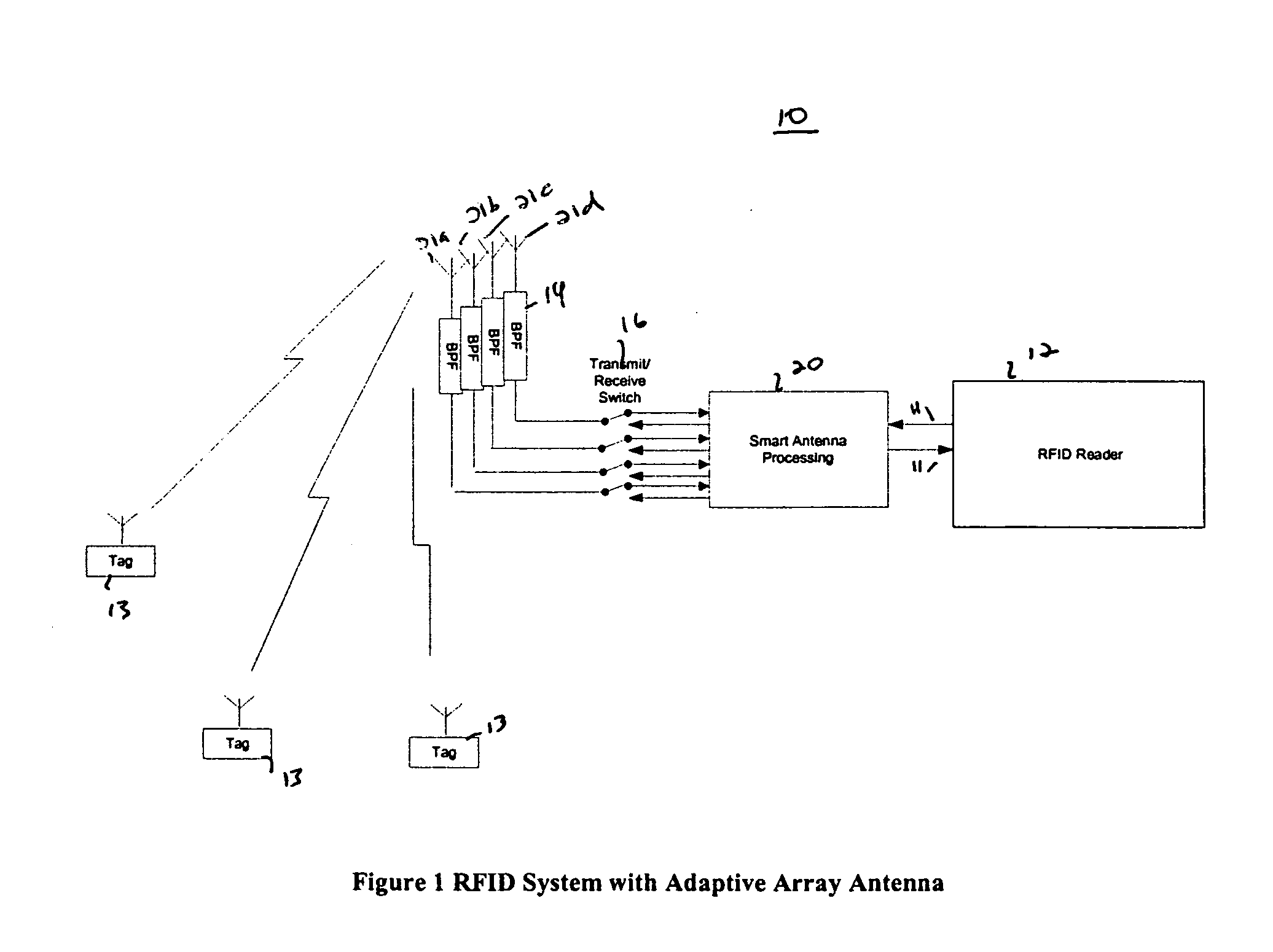
[0014]FIG. 1 is a schematic diagram of Radio Frequency Identification (RFID) system 10 in accordance with the teachings of the present invention.

[0015] RFID reader 12 transmits and receives signals 11 to and from RFID tags 13. RFID reader 12 includes smart antenna processing module 20 for adaptively combining signals from a plurality of antennas 21a-21d. Smart antenna processing module 20 is connected by transmit receive switches 16a-16d and bandpass filters 14a-14d to antennas 21a-21d. Smart antenna processing module 20 can combine signals 11 to maximize the received signal-to-noise ratio (SNR) based weights determined by maximal ratio combining (MRC).

[0016] There are various ways to ...


PUM


Abstract

The present invention relates to use of a smart antenna for a RF reader on a Radio Frequency Identification (RFID) system to significantly increase the operating range of the RFID system. The smart antenna can be an adaptive antenna array. The smart antenna comprises a plurality of antenna elements and, by combining the signals from multiple antenna elements, significantly increases the received signal-to-noise ratio. In a noise limited environment, combining the signals to maximize the received signal-to-noise ratio can be based on the maximal ratio combining (MRC) principle. To achieve the best signal quality, the received signal from each antenna can be phase-shifted such that the resultant signals from all antennas are in phase. In addition, the signal from each antenna can be scaled in amplitude based on the square root of its received signal-to-noise ratio.

Description

CROSS REFERENCE TO RELATED APPLICATION [0001] This application claims the benefit of U.S. Provisional Patent Application No. 60 / 528,349 filed Dec. 10, 2003 the entirety of which is hereby incorporated by reference into this application.BACKGROUND OF THE INVENTION [0002] 1. Field of the Invention [0003] This invention relates generally to a Radio Frequency Identification (RFID) system. More particularly, it relates to an adaptive antenna array for a RF reader for increasing the operating range of the RFID system. [0004] 2. Description of Related Art [0005] A conventional Radio Frequency Identification (RFID) system consists of a reader and a plurality of RF tags. The RF reader transmits a radio signal containing a unique identification (ID) to poll one of a plurality of RF tags. The RF tag polled responds by sending back a radio signal. A variety of RFID systems have been used in different applications such as warehouse inventory control systems. [0006] There are two types of convent...

Claims


Application Information

Patent Timeline
Patent Type & Authority Applications(United States)
IPC IPC(8): H01Q1/22H01Q3/26H04B1/00H04B7/08
CPCG06K7/10356H01Q1/2208H04B7/0857H04B7/0848H01Q3/2605
Inventor WANG, JAMES JUNE-MINGWINTERS, JACKWARNER, ROBERT
Owner RENDA TRUST
Why Eureka
Try Eureka