Video signal processing apparatus, TV receiver using the same, and video signal processing method

a video signal and processing apparatus technology, applied in the field of video signal processing apparatus and tv receiver using the same, can solve the problems of large image amplitude and difficult to see images in some images, and achieve the effect of reducing noise and high picture quality

Active Publication Date: 2005-06-16
MAXELL HLDG LTD
View PDF10 Cites 40 Cited by
  • Summary
  • Abstract
  • Description
  • Claims
  • Application Information

AI Technical Summary

Benefits of technology

[0009] According to this invention, it becomes possible to ...

Problems solved by technology

When the signal gain is increased, however, then the image amplitude becomes large and in addition noise components contained in the image are also amplified.
In an apparatus having these two compensation functions, therefore, the noise components becomes larger in a state in which the compensation for increasing the contrast is being conducte...

Method used


Image

  • Video signal processing apparatus, TV receiver using the same, and video signal processing method
  • Video signal processing apparatus, TV receiver using the same, and video signal processing method
  • Video signal processing apparatus, TV receiver using the same, and video signal processing method

Examples


Embodiment Construction

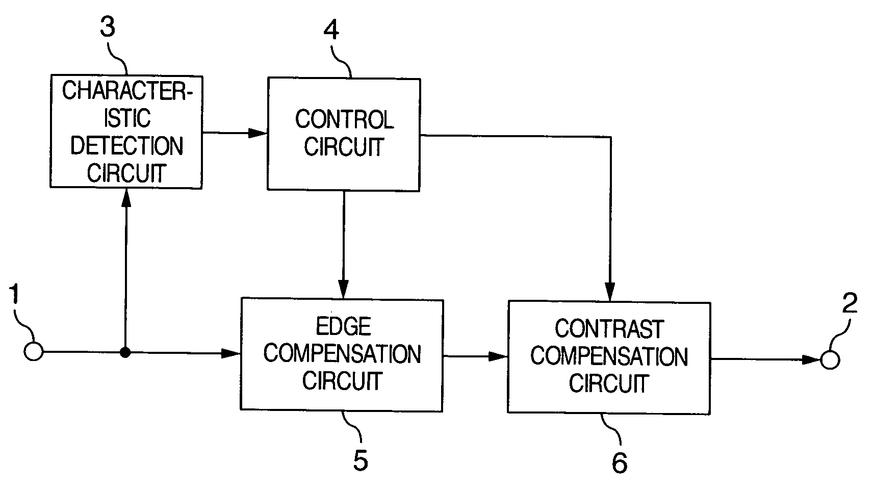
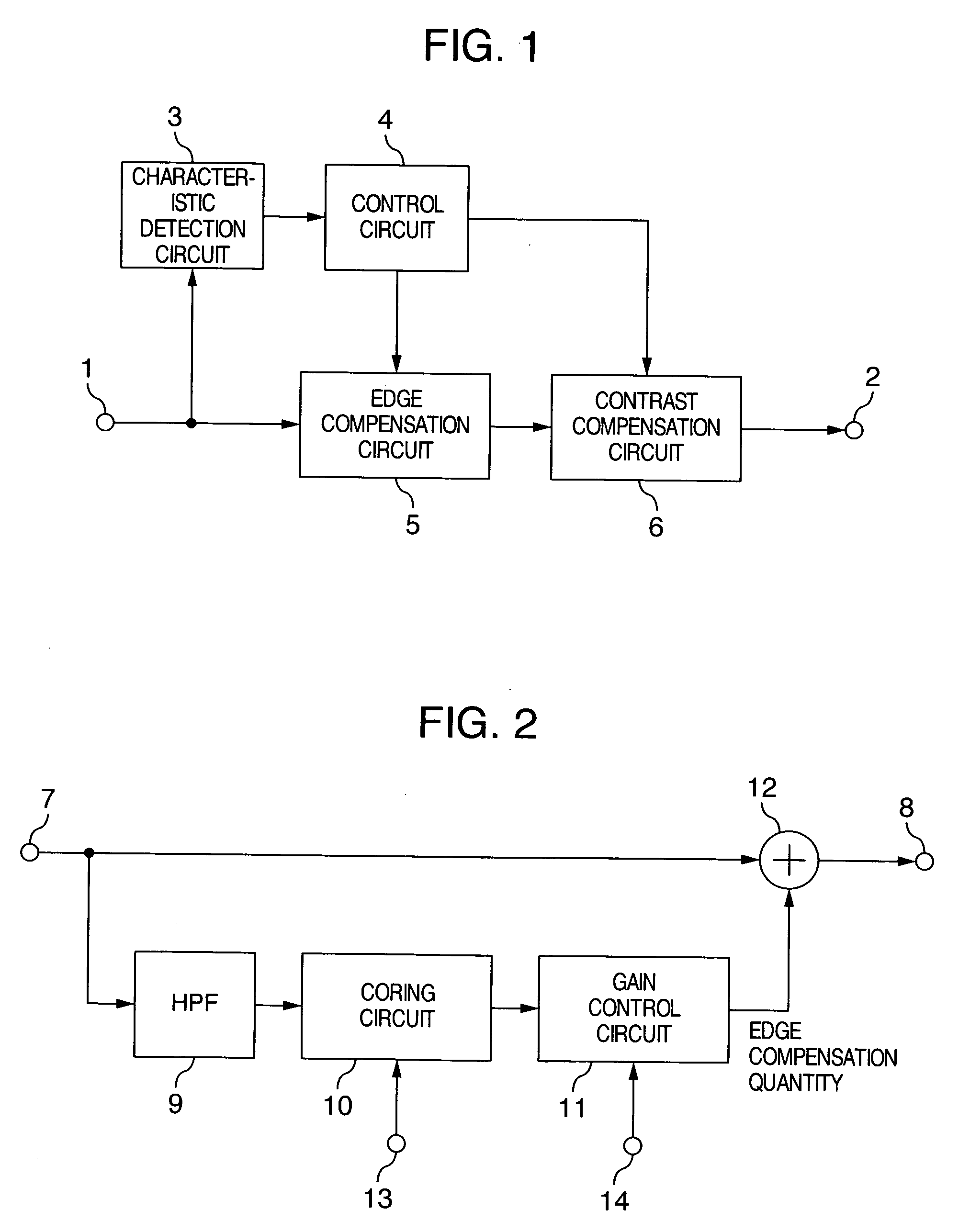
[0020] Hereafter, preferred embodiments of this invention will be described. FIG. 1 shows one embodiment of a video signal processing apparatus according to this invention. The video signal processing apparatus is used in apparatuses such as TV receivers. However, the video signal processing apparatus can be used in an apparatus that does not have a display unit, such as a VTR, DVD apparatus, or a digital tuner called set top box (STB) that receives a digital TV broadcast signal, in the same way.

[0021] In FIG. 1, a video signal having a digital form (hereafter simply referred to as video signal) is inputted to a video input terminal 1, and supplied to an image characteristic detection circuit 3 and an edge correction circuit 5. The characteristic detection circuit 3 detects a characteristic of the input video signal, for example, luminance distribution (a histogram) corresponding to one screen of the video signal, and outputs the detection result to a control circuit 4. The control...


PUM


Abstract

A video signal processing apparatus includes a characteristic detection circuit for detecting luminance distribution corresponding to one frame of a video signal, a contrast compensation circuit for compensating contrast of the video signal, an edge compensation circuit for compensating an edge portion of the video signal, and a control circuit for determining a luminance range to be controlled on the basis of the luminance distribution detected by the characteristic detection circuit, and controlling the contrast compensation circuit and edge compensation circuit to conduct predetermined compensation on the video signal belonging to the luminance range. The control circuit controls the contrast compensation circuit to increase contrast for the video signal in the luminance range as compared with the video signal in other regions, and controls the edge compensation circuit to make an edge compensation quantity for the video signal in the luminance range smaller as compared with other regions.

Description

INCORPORATION BY REFERENCE [0001] The present application claims priority from Japanese application JP2003-411178 filed on Dec. 10, 2003, the content of which is hereby incorporated by reference into this application. BACKGROUND OF THE INVENTION [0002] This invention relates to a video signal processing apparatus that conducts signal processing such as contrast adjustment and edge compensation on a video signal, a TV receiver using such a video signal processing apparatus, and a video signal processing method. [0003] As a conventional technique concerning the contrast compensation function in TV receivers, a technique of detecting a maximum level and a minimum level of a video luminance signal and an average luminance level and controlling the contrast compensation on the basis of these levels is known as described in, for example, Japanese Patent No. 3,215,400. As a conventional technique concerning the sharpness adjustment function, i.e., the edge compensation function, a techniqu...

Claims


Application Information

Patent Timeline
IPC IPC(8): H04N5/208H04N5/57
CPCH04N5/208H04N21/44008H04N21/4318H04N5/57
Inventor NAKAJIMA, MITSUOTSURU, YASUTAKAMATONO, TAKAAKITAKATA, HARUKI
Owner MAXELL HLDG LTD
Why Eureka
Try Eureka