Computerized virtual reflex perimetry

a technology of automated visual field and reflex perimetry, which is applied in the field of methods and systems for automated visual field (perimetry) testing, can solve the problems of impracticality of large-scale use, inability to effectively connect both remote and local sites in the real world, and inability to use a moving fixation point to increase the degree of viewable visual field on a small monitor or compliance during testing, etc., to achieve convenient and convenient specification parameters, the effect of easy standardization

Inactive Publication Date: 2005-06-16
IANCHULEV TSONTCHO +2
View PDF14 Cites 19 Cited by
  • Summary
  • Abstract
  • Description
  • Claims
  • Application Information

AI Technical Summary

Benefits of technology

[0026] Our invention is distinct in its systematic virtual design. It uses internet technology for in-demand delivery but is fully functional without a direct link to the internet since it can be also be installed from a disc or other recordable media and be completely functional without external electronic loop. It uses simple, easily achievable specification parameters that are readily standardized among numerous types of monitor display devices to achieve clinically relevant results that have been validated in a clinical trial (reference). This system is accessible to almost anyone with internet access or the most bas...

Problems solved by technology

Although dedicated visual field systems produce consistent results that can be compared over time, they are impractical to use on a large scale, such as for population based screening, where it is estimated that over 50% of those with glaucoma are unaware of their disease.
The problems inherent in establishing and maintaining such a complex system to cohesively connect both the remote and local site in the real world would be difficult to accomplish in a practical fashion.
The use of a moving fixation point to increase degrees of viewable visual field on a small monitor or compliance during test...

Method used


Image

  • Computerized virtual reflex perimetry
  • Computerized virtual reflex perimetry
  • Computerized virtual reflex perimetry

Examples


Embodiment Construction

[0037] What follows describes the preferred embodiment of our system but does not in any way limit the myriad of ways our system and its components can be modified, upgraded or altered without violating its form or function. It would be impossible to fully and completely convey all the variations in a few pages of text and diagrams but anyone skilled in the arts would readily recognized the possibilities inherent in our system.

[0038] Our system relies on proprietary, clinically validated systems integration among various components consisting of two primary parts: [0039] 1) Internet-based software that is deployable via the internet or on electronic media such as compact discs. [0040] 2) Computer system with a CPU, storage device, viewing surface, browser interface, and input device such as a keyboard, mouse, or trigger switch.

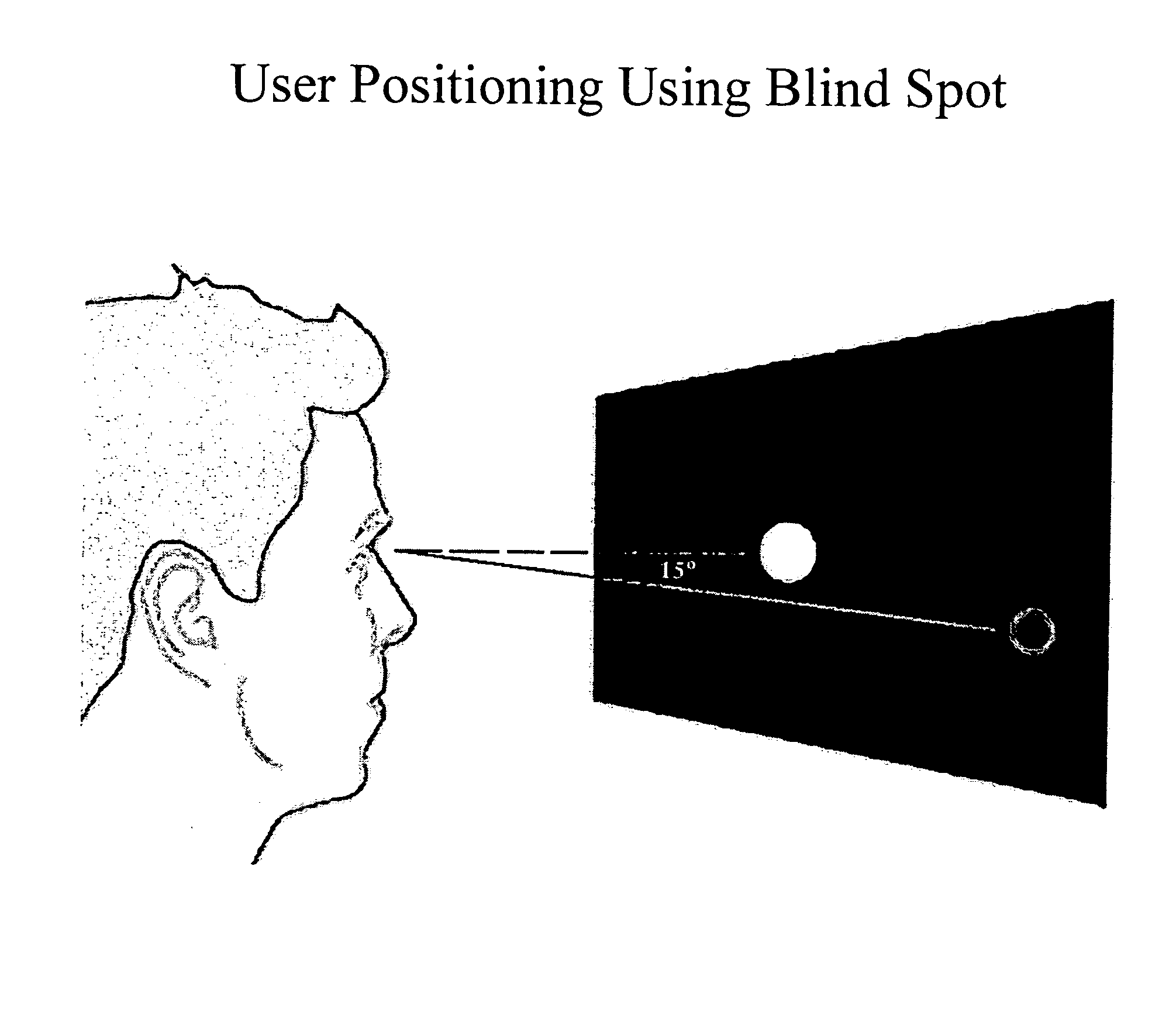
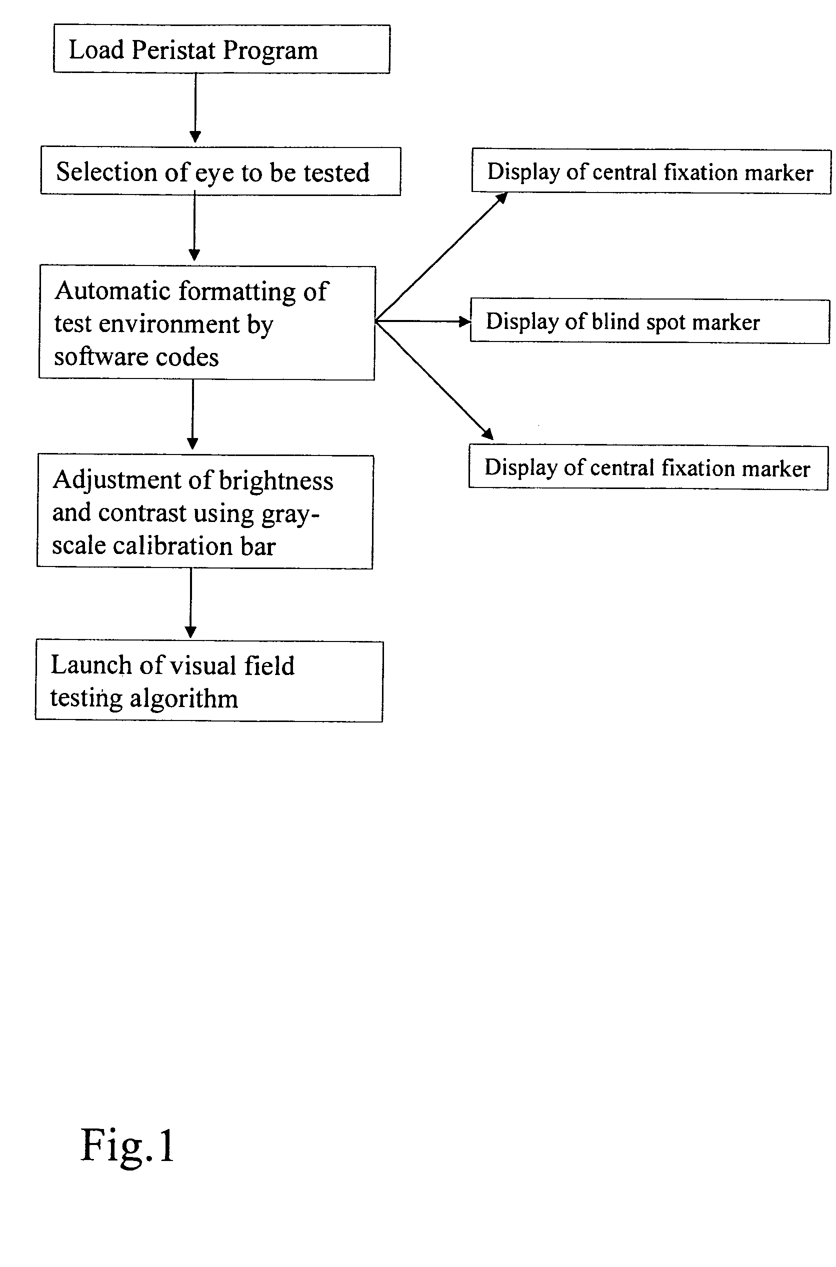
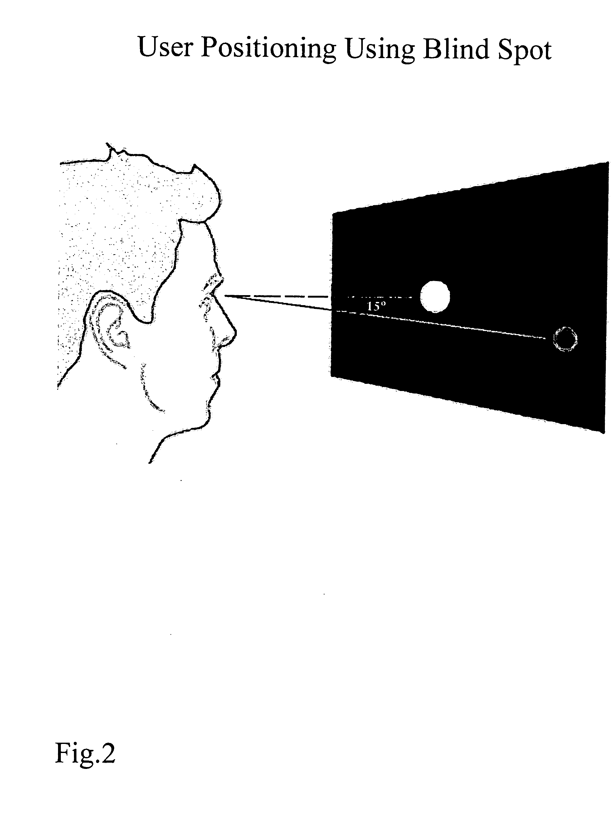
[0041] In detail, FIG. 1 outlines the basic steps involved during visual field testing with our system. The software is easily downloading via the internet ...


PUM


Abstract

An automated unaided virtual perimetry system and underlying method for relative-threshold contrast sensitivity interrogation of the visual field via algorithmic presentation of visual stimuli on a screen and subsequent analysis of test response data for the detection of pathophysiologic scotomas as well response time registration and analysis for visual motor reflex testing. Launch of system via access from a remote server or direct installation of systems technology allows seamless capability at the local computer system to instruct, administer, and analyze output of stimuli and input of responses of test subjects or subjects independent of external input or control. Specific algorithmic test environment is designed to achieve comparable clinical efficacy and diagnostic utility to office-based perimetry system.

Description

CROSS-REFERENCE TO RELATED APPLICATION [0001] This application claims priority to U.S. provisional application Ser. No. 60 / 506,845 filed Sep. 30th, 2003.TECHNICAL FIELD [0002] This invention relates to the methods and systems for automated visual field (perimetry) testing. BACKGROUND OF PRESENT INVENTION [0003] Recent progress in medical science has enabled significant extension to average life expectancy with a marked improvement in the activity and lifestyle of the elderly. Octogenarians drive and perform more and more complex and involved tasks of daily life. These higher demands on performance necessitate the development of a system for monitoring and benchmarking of visual and reflex abilities. Without an adequate visual capacity, such as an intact and physiologic visual field, or an unimpaired visual motor reflex, the ability to drive, fly, or perform other ordinary activities could be greatly diminished. As a result, the safety and wellbeing of the public can be affected. [00...

Claims


Application Information

Patent Timeline
IPC IPC(8): A61B3/024
CPCA61B3/024
Inventor IANCHULEV, TSONTCHOPHAM, PETERMAKAROV, VLADIMIR
Owner IANCHULEV TSONTCHO
Why Eureka
Try Eureka