Methods and apparatus for temperature measurement and control in electromagnetic coils

a technology of electromagnetic coils and temperature measurement, applied in the direction of heat measurement, optical radiation measurement, instruments, etc., can solve the problems of difficult installation, adversely affecting imaging performance, and interfering with the electromagnetic characteristics of gradient coils

Inactive Publication Date: 2005-06-16
GE MEDICAL SYST GLOBAL TECH CO LLC
View PDF18 Cites 29 Cited by
  • Summary
  • Abstract
  • Description
  • Claims
  • Application Information

AI Technical Summary

Problems solved by technology

However, these devices interfere with the electromagnetic characteristics of the gradient coils and are rather difficult to install.
In addition, very small location shifts (such as 0.1 mm) for any of the gradient coils (X, Y or Z) resulting from the installation and use of these devices strongly affect the magnetic field in a field of interest and thus adversely affect imaging performance.
Althoug...

Method used


Image

  • Methods and apparatus for temperature measurement and control in electromagnetic coils
  • Methods and apparatus for temperature measurement and control in electromagnetic coils
  • Methods and apparatus for temperature measurement and control in electromagnetic coils

Examples


Embodiment Construction

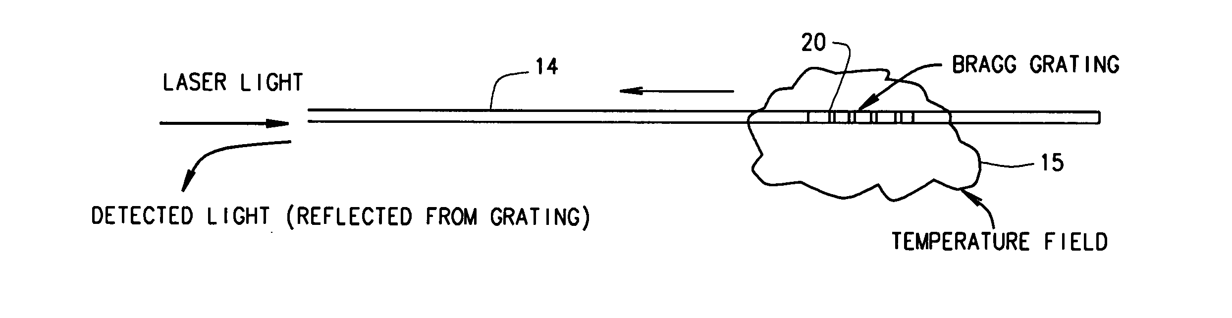
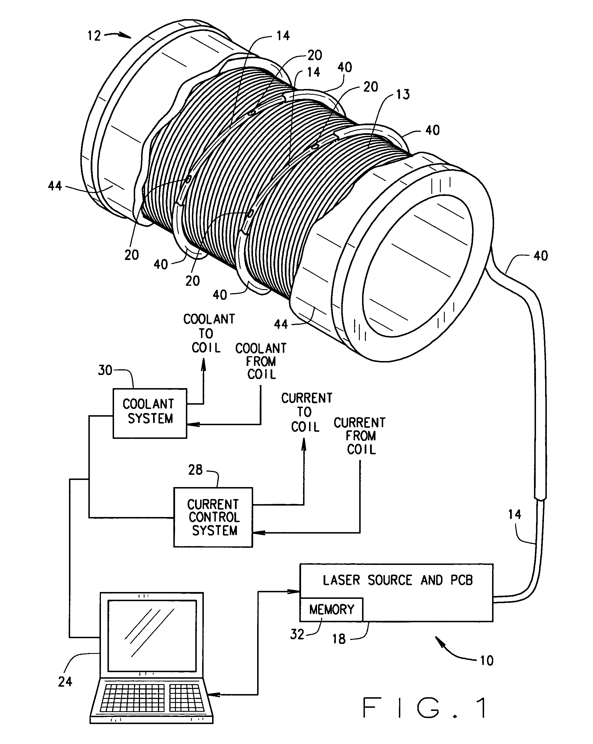
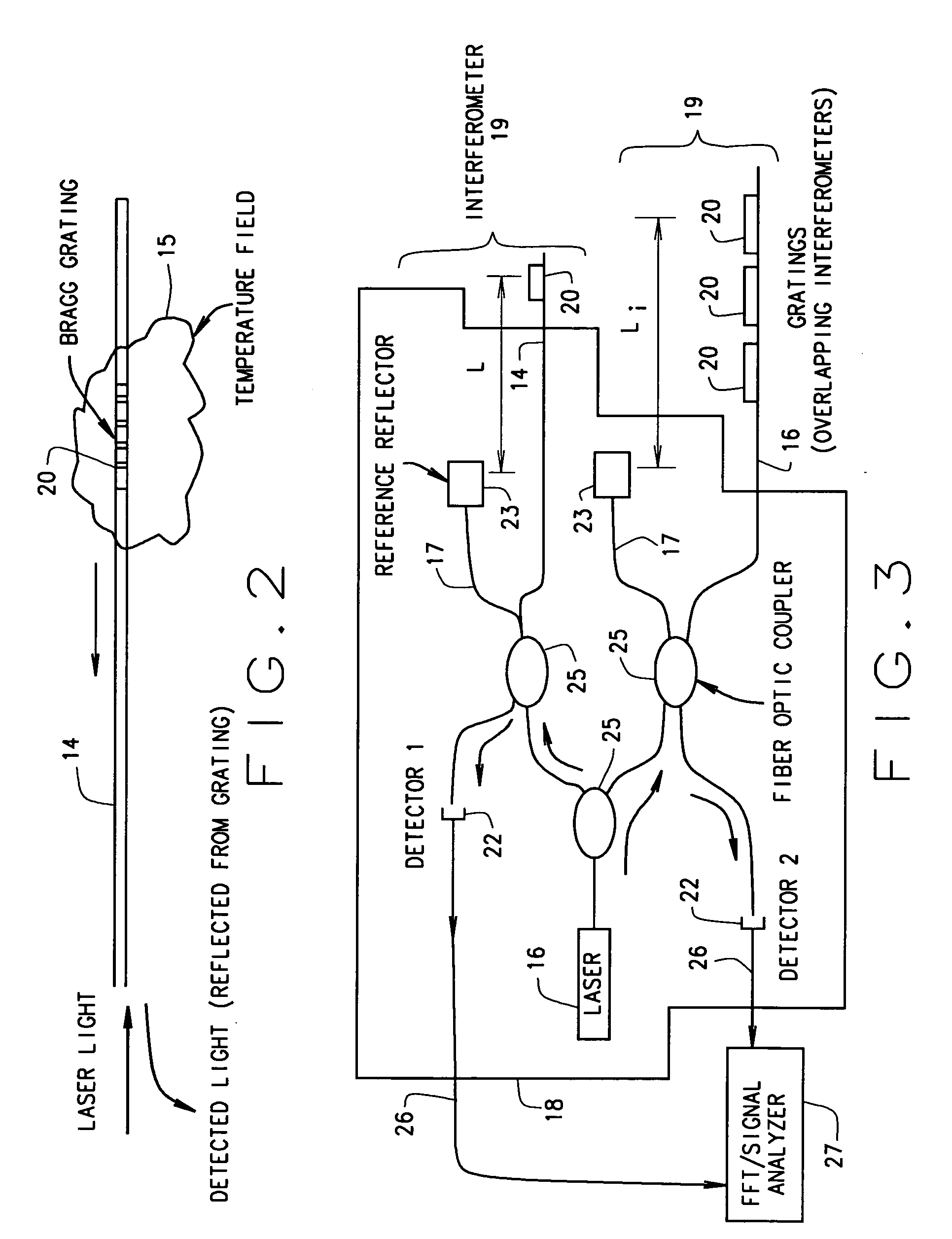
[0011] In some configurations of the present invention and referring to FIGS. 1, 2 and 3, a fiber-optic based distributed temperature measurement system 10 for an electromagnetic coil assembly 12 facilitates measurement of temperatures within electromagnetic coil assembly 12. One or more non-magnetic (e.g., non-conducting and non-metallic) sheaths 40 are embedded in, under, and / or wound on top of electromagnetic coil assembly 12. (FIG. 1 shows a configuration having a single sheath 40 wound over windings 13 of electromagnetic coil assembly 12 to more clearly show sheath 40, fiber optic fiber 14, and Bragg gratings 20.) In some configurations, sheaths 40 are wrapped in a radial direction, as shown in FIG. 1, or in a z-direction (i.e., parallel to the axis of the electromagnetic coil assembly 12). Also in some configurations, the fibers can be wrapped or snaked multiple times over selected locations of electromagnetic coil locations 12 that are considered significant for monitoring pu...


PUM


Abstract

A method for monitoring temperature in at least one location of an electromagnetic coil assembly having at least one electrical winding. The method includes passing a light through a non-magnetic optical fiber inserted into a sheath that is wound with the electrical winding. The sheath is wound and cast with the electromagnetic coil assembly, and the optical fiber is slidably inserted therein. The optical fiber has a core containing at least a first Bragg grating etched therein. The method further includes detecting a wavelength of light reflected from the first Bragg grating and determining a temperature of the electromagnetic coil assembly at a location of the first Bragg grating utilizing the detected wavelength of the light reflected from the first Bragg grating.

Description

BACKGROUND OF THE INVENTION [0001] This invention relates generally to methods and apparatus for measuring temperatures in electromagnetic coil assemblies that are particularly suitable for use with coil assemblies having high current electromagnetic windings. Examples of such coils are found in magnetic resonance imaging apparatus and elsewhere. [0002] At least one known magnetic resonance imaging (MRI) apparatus utilizes thermocouples, resistors, and / or resistive thermal devices (RTDs) to detect gradient coil temperatures. However, these devices interfere with the electromagnetic characteristics of the gradient coils and are rather difficult to install. In addition, very small location shifts (such as 0.1 mm) for any of the gradient coils (X, Y or Z) resulting from the installation and use of these devices strongly affect the magnetic field in a field of interest and thus adversely affect imaging performance. As a result, the temperature distribution of MR gradient coils in at lea...

Claims


Application Information

Patent Timeline
IPC IPC(8): G01J3/12G01J5/00G01K11/00G01K11/32
CPCG01K11/3206G01K11/00
Inventor RAJENDRAN, VEERA PALANIVELUARIK, MEHMETAKSEL, BULENT
Owner GE MEDICAL SYST GLOBAL TECH CO LLC
Why Eureka
Try Eureka