
Photovoltaic Module Failure Detection Devices and Methods

a technology of photovoltaic modules and failure detection devices, applied in the testing of individual semiconductor devices, pv power plants, instruments, etc., can solve the problems of increasing the incidence of diode related failures in modern photovoltaic modules, and achieve the effects of improving output, low cost, and effective devices

Inactive Publication Date: 2011-04-21
BP CORP NORTH AMERICA INC
View PDF16 Cites 29 Cited by
  • Summary
  • Abstract
  • Description
  • Claims
  • Application Information

AI Technical Summary

Benefits of technology

This patent relates to devices and methods for detecting failures of photovoltaic module diodes. The invention provides reliable, low-cost, and effective devices and methods to improve the performance and reliability of photovoltaic modules. The methods and devices provide visual indication of diode temperatures and detection of diode failures during installation, pre-commission checking, commissioning, operation, and maintenance. The invention includes the use of temperature indication devices within the photovoltaic modules, which can help ensure proper installation, improve output, expedite maintenance, increase safety, raise reliability, and the like. The patent also includes the use of transparent front and back sheets with the photovoltaic modules, as well as the fabrication process of the photovoltaic modules. Overall, the invention enhances the reliability and performance of photovoltaic modules.

Problems solved by technology

Due to the electrical configuration in modern modules and the electrical limitations of the diodes, there has been an increased incidence of diode related failures in modern photovoltaic modules.

Method used


Image

  • Photovoltaic Module Failure Detection Devices and Methods
  • Photovoltaic Module Failure Detection Devices and Methods
  • Photovoltaic Module Failure Detection Devices and Methods

Examples


example

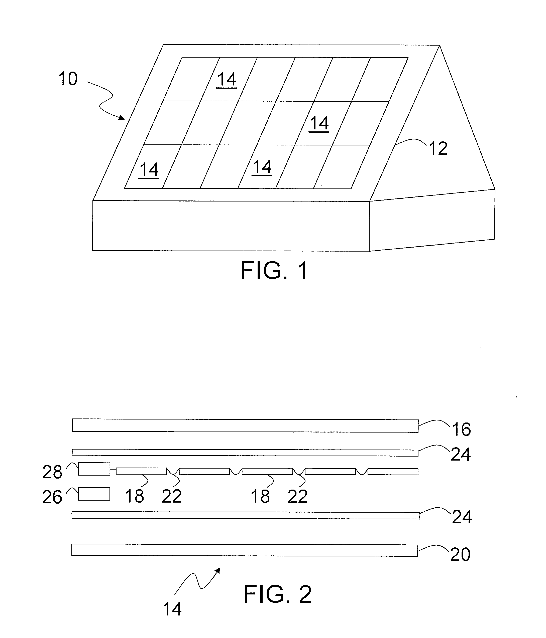
[0127]A mock photovoltaic module without working solar cells was fabricated as below. The mock photovoltaic module included blank solar cells, a printed circuit board with pre-mounted diodes, and temperature indication devices (temperature dots). These components were laminated between a transparent front sheet and a back sheet to form the mock photovoltaic module. The temperature dots successfully laminated into the mock photovoltaic module without bubbles and / or blistering. Embodiments with temperature indication devices to detect a temperate of other portions of and / or surroundings of the photovoltaic module are within the scope of this invention.

[0128]A reversible temperature indication device and a non-reversible temperature indication device were placed on the top side of the printed circuit board on top of and / or near the diodes. The reversible temperature indication devices can be useful for repeatedly detecting hot diodes in-situ while the photovoltaic module generates elec...


PUM

PropertyMeasurementUnit
temperatureaaaaaaaaaa
sizeaaaaaaaaaa
sizeaaaaaaaaaa

Abstract

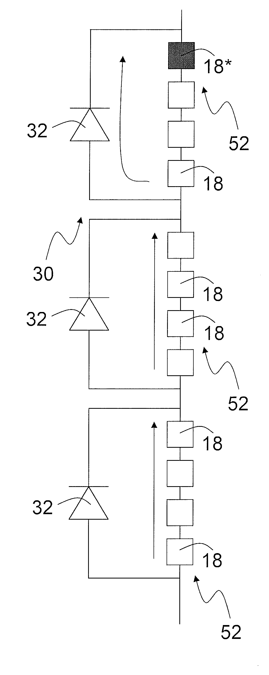
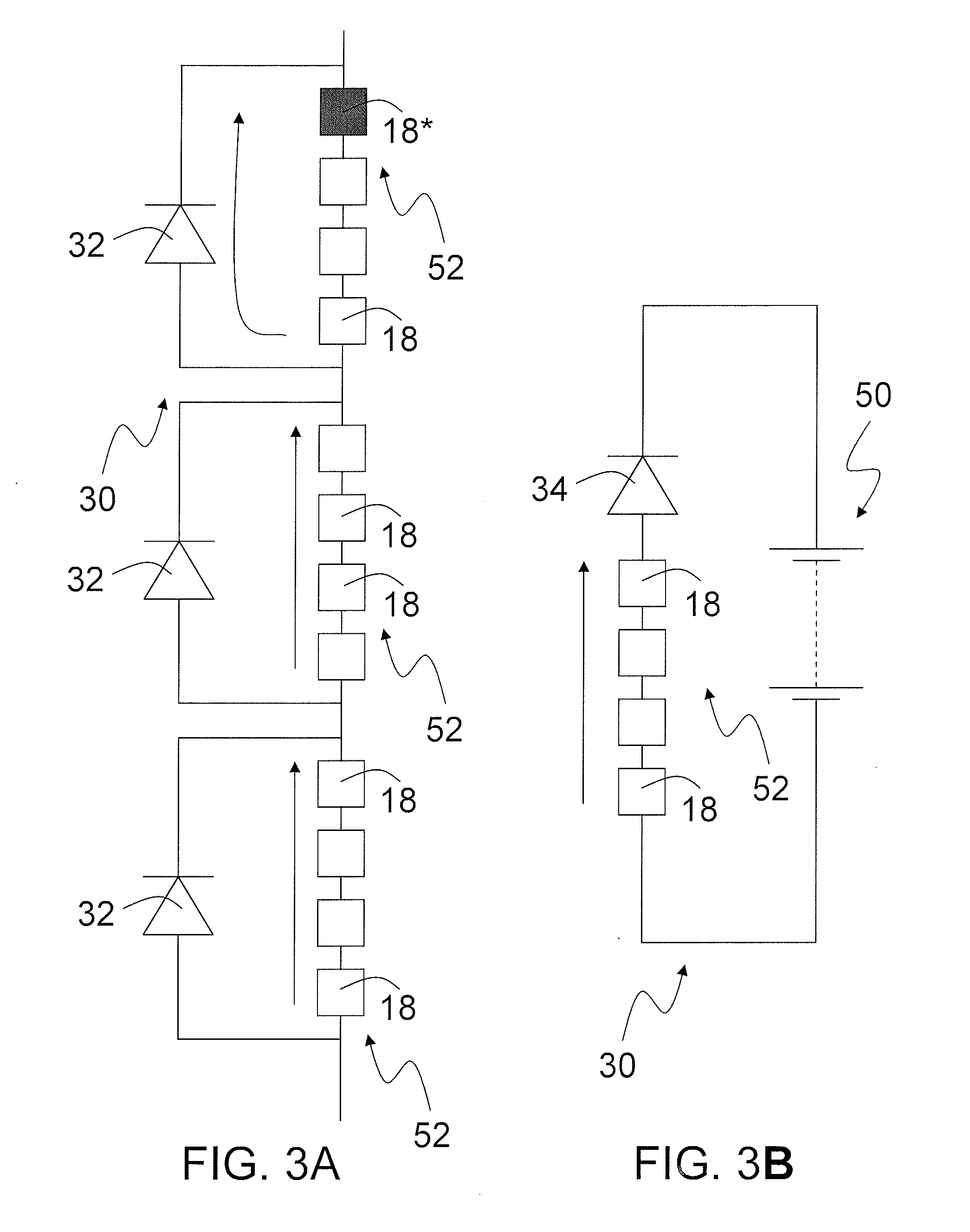
Photovoltaic module failure detection devices and methods provide reliable, low cost, and effective solutions with visual indication of a temperature of diodes during installation, commissioning, operation, and / or maintenance. Indication of diode temperatures and / or detection of diode failures assures proper installation, improves output, expedites maintenance, increases safety, and / or raises reliability. A photovoltaic module for converting light into electricity includes one or more solar cells, and a transparent front sheet disposed over the one or more solar cells. The photovoltaic module includes a back sheet opposite the transparent front sheet, and one or more electrical circuits with one or more diodes connected to at least a portion of the one or more solar cells. The module includes one or more temperature indication devices in communication with at least a portion of the one or more diodes and disposed between the transparent front sheet and the back sheet.

Description

[0001]This application claims the benefit of U.S. Provisional Application No. 61 / 253,648 filed Oct. 21, 2009, the entirety of which is expressly incorporated herein by reference.BACKGROUND[0002]1. Field of the Invention[0003]This invention relates to photovoltaic module failure detection devices and methods.[0004]2. Discussion of Related Art[0005]Photovoltaic devices seek to convert solar energy into electricity. There has been much effort and investment into improving photovoltaic devices and related components to improve efficiency, power output, reliability, and safety. To achieve these functions, photovoltaic devices are generally protected by incorporating one or more diodes into the electrical circuit of the photovoltaic device. Due to the electrical configuration in modern modules and the electrical limitations of the diodes, there has been an increased incidence of diode related failures in modern photovoltaic modules. Therefore, there remains a need and a desire for reliabl...

Claims


Application Information

Patent Timeline
Patent Type & Authority Applications(United States)
IPC IPC(8): H01L31/042H01L31/18G01R31/26
CPCY10T29/49355H02S50/10Y02E10/50
Inventor XIA, ZHIYONGDANIELS, ERIC E.CUNNINGHAM, DANIEL W.
Owner BP CORP NORTH AMERICA INC
Learn More