Echo canceler circuit and method

a canceler and circuit technology, applied in the field of communication systems, can solve problems such as inability to work normally, inability to cancel, and change the data of pre-echo canceler uplink, and the estimation of echo data may contain errors

Active Publication Date: 2005-06-16
CONTINENTAL AUTOMOTIVE SYST INC
View PDF17 Cites 45 Cited by
  • Summary
  • Abstract
  • Description
  • Claims
  • Application Information

AI Technical Summary

Problems solved by technology

An echo signal corresponding to the delayed transmitted signal is perceived as annoying to the near end user and in some cases can result in an unstable condition known as “howling.”
However, the pre-echo canceler uplink data may change due to variations in the acoustic coupling faster or beyond the capabilities of the echo canceler adaptive filter.
As a result, due to imperfect knowledge of the network medium and the acoustic coupling channel creating the echo signal, the estimated echo data may contain errors.
Additionally, if the amplifier gain is increased, the downlink signal may cause the received microphone signal to be so great that the reduced echo return loss may significantly reduce the effectiveness of the adaptive filter and possibly cause the adaptive filter to become ineffective or possibly unstable.
Consequently, the adaptive filter under this condition may actually cause the uplink signal to also become degraded, unstable, or corrupted.
As a result, the corrupted post-echo canceler uplink data will cause annoying loud noises at the far end.
As a result, the uplink data may be improperly attenuated causing the near end user not to be heard by the far end user because the echo canceler incorrectly interpreted an increase in post-echo canceler uplink data power due to an increase in downlink data power as an increase in acoustic coupling.
However, since the echo canceler adaptive filter is typically implemented in a processing device, increasing the number of coefficients may result in an increased processor load, and may reduce the rate of adaptation of the echo canceler adaptive filter and increase power consumption.
As a result, a more complex and more costly echo canceler adaptive filter is required to satisfy the required processor load.

Method used


Image

  • Echo canceler circuit and method
  • Echo canceler circuit and method
  • Echo canceler circuit and method

Examples


Embodiment Construction

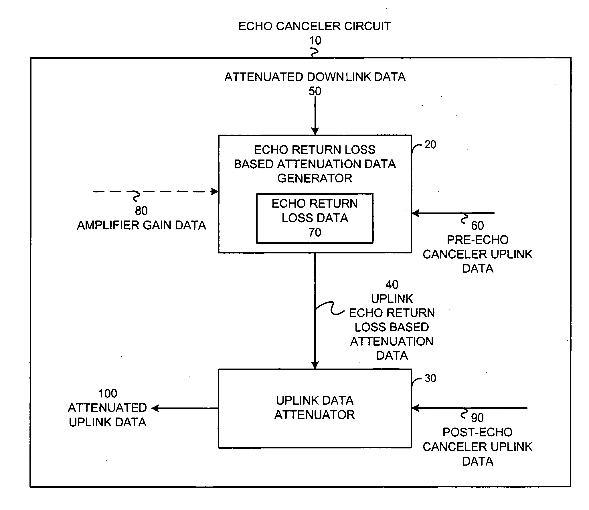
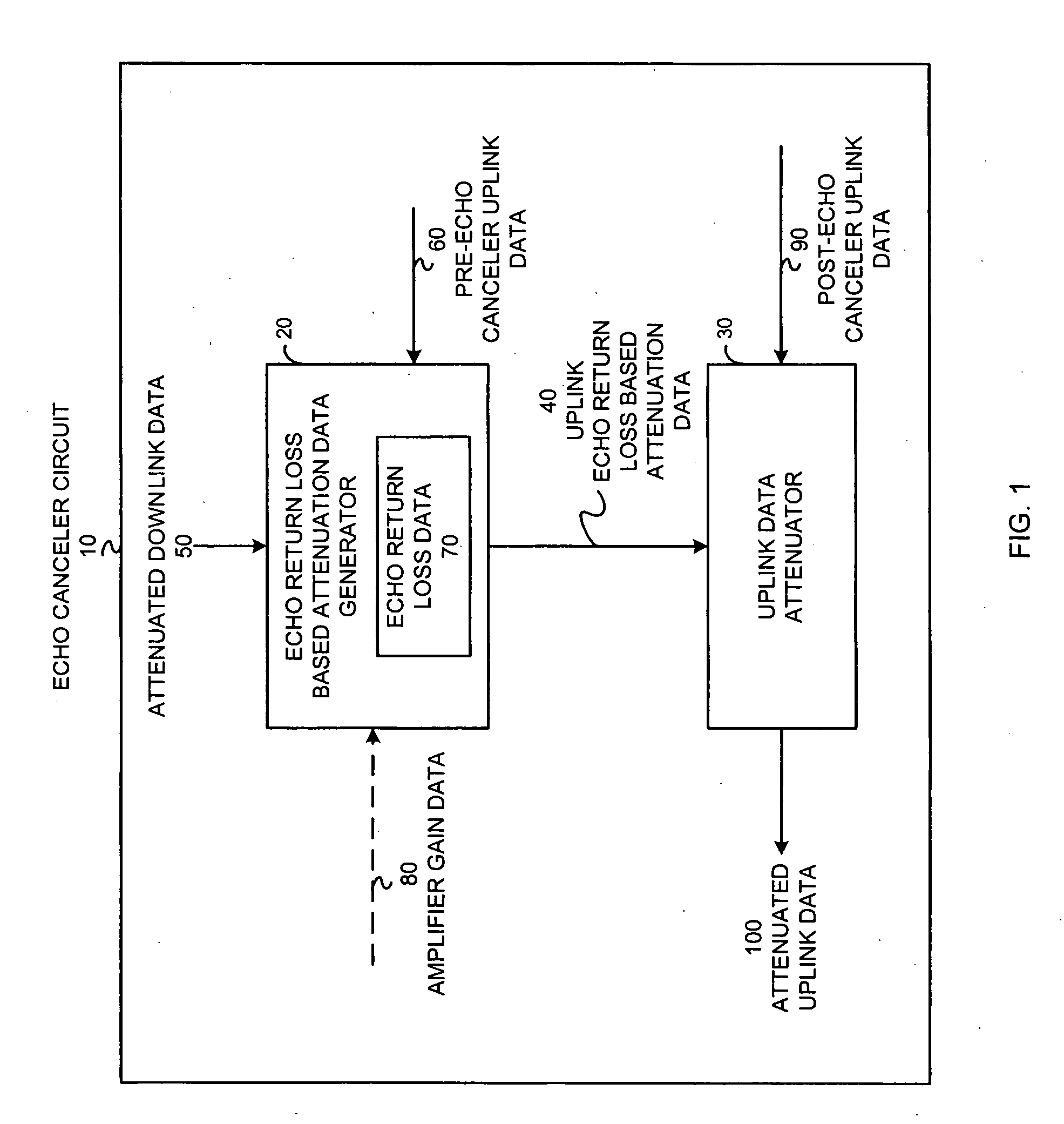
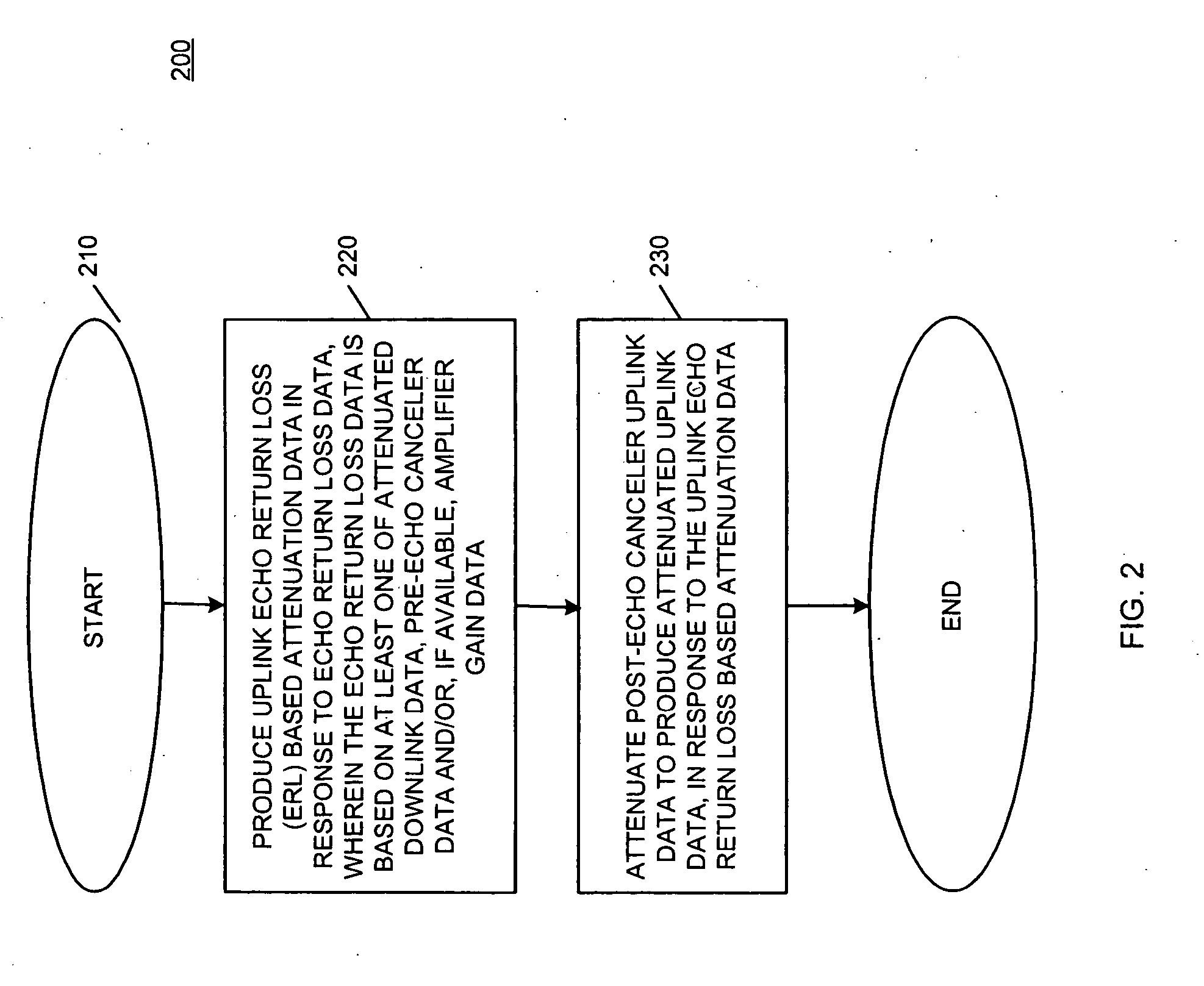
[0020] An echo canceler circuit and method attenuates at least post-echo canceler uplink data to produce attenuated uplink data in response to echo return loss data. The echo return loss data, according to one embodiment, is the ratio between the attenuated downlink data provided to the amplifier in an audio system and the pre-echo canceler uplink data received by a microphone. The echo canceler circuit includes an echo return loss based attenuation data generator and at least an uplink data attenuator. The echo return loss based attenuation data generator produces the uplink echo return loss based attenuation data in response to the echo return loss data, wherein the echo return loss data is based on at least one of: attenuated downlink data, pre-echo canceler uplink data and amplifier gain data. The uplink data attenuator attenuates the post-echo canceler uplink data to produce the attenuated uplink data based on the uplink echo return loss based attenuation data.

[0021] Among oth...


PUM


Abstract

An echo canceler circuit (10) and method attenuates at least post-echo canceler uplink data (90) to produce attenuated uplink data (100) in response to uplink echo return loss based attenuation data (40). The echo canceler circuit (10) includes an echo return loss based attenuation data generator (20) and at least an uplink data attenuator (30). The echo return loss based attenuation data generator (20) produces the uplink echo return loss based attenuation data (40) in response to echo return loss data (70). The echo return loss data (70) is based on at least one of: attenuated downlink data (50), pre-echo canceler uplink data (60), and/or amplifier gain data (80). The uplink data attenuator (30) attenuates the post-echo canceler uplink data (90) to produce attenuated uplink data (100) based on the uplink echo return loss based attenuation data (40).

Description

FIELD OF THE INVENTION [0001] The invention relates generally to communication systems and more particularly to echo cancelers and echo cancellation methods. BACKGROUND OF THE INVENTION [0002] Echo in a communication system is commonly characterized as the return of a part of a transmitted signal from an end user back to the originator of the transmitted signal after a delay period. As is known in the art, a near end user transmits an uplink signal to a far end user. Conversely, the near end user receives a downlink signal from the far end user. Echo at the near end occurs when the near end user originates an uplink signal on the uplink path, and a part of the transmitted signal is reflected at the far end as an echo signal on the downlink path back to the near end. Echo at the far end occurs when the far end user originates a downlink signal on the downlink path, and a part of the transmitted signal is reflected at the near end, as an echo signal on the uplink path back to the far ...

Claims


Application Information

Patent Timeline
Patent Type & Authority Applications(United States)
IPC IPC(8): H04B3/20H04B3/23H04M9/08
CPCH04M9/082H04B3/20
Inventor PIKET, JAMES B.OWENS, KEITH L.SPRINGFIELD, CHRISTOPHER W.
Owner CONTINENTAL AUTOMOTIVE SYST INC
Why Eureka
Try Eureka