
Molded article with foam-encased reinforcing member

a technology of reinforcing member and molded article, which is applied in the field of molded polymer articles, can solve the problems of differential shrinkage of these members, affecting the internal stress of the molded article, and presenting certain additional challenges to the integrated structural fram

Inactive Publication Date: 2005-06-16
MITY-LITE
View PDF30 Cites 13 Cited by
  • Summary
  • Abstract
  • Description
  • Claims
  • Application Information

AI Technical Summary

Benefits of technology

[0008] It has been recognized that it would be advantageous to develop a molded article with a foam core and an encased reinforcing member that resists post-molding shrinkage-related deformation.
[0009] It would also be advantageous to develop a molded article wherein there is minimal internal stress created by differential post-molding shrinkage of the foam core and frame.
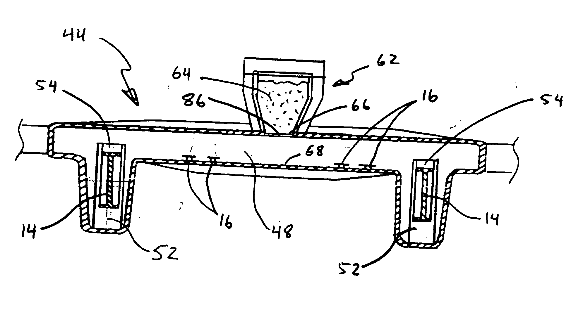
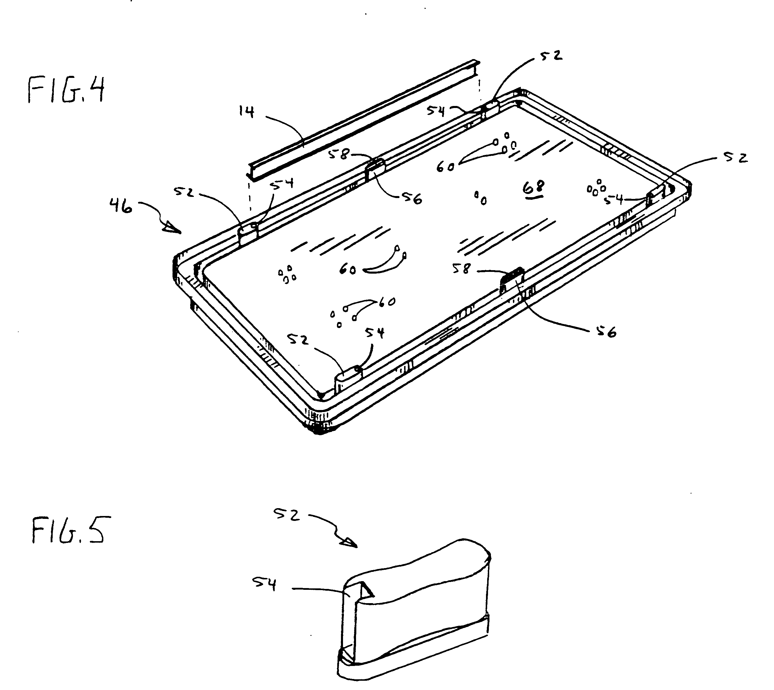
[0011] In accordance with one aspect thereof, the invention provides a molded article, having a body of polymer material, formed in a mold, an elongate reinforcing member, having an end, substantially encased within the body of polymer material during molding thereof, and a slip zone around the end of the reinforcing member. The body of polymer material and the reinforcing member have unique post-molding shrinkage properties. The reinforcing member has a surface that substantially eliminates adhesion with the polymer material, so as to enable displacement of the reinforcing member with respect to contacting polymer material. The slip zone defines a void in the body of polymer material, such that post-molding shrinkage of the polymer material imposes substantially no stress on the end of the reinforcing member.

Problems solved by technology

Unfortunately, an integrated structural frame presents certain additional challenges with one-pass molded articles.
After the molding process is complete, the polymer table will tend to shrink significantly, both because of cooling and because of phase-change densification of the polymer materials.
If the polymer material bonds or adheres to the frame, the differential shrinkage of these members can produce significant internal stress inside the molded article.
The result of these factors is that the molded article is much more likely to experience undesirable post-molding deformation because of the internal stress and differential shrinkage of the components of the article.

Method used


Image

  • Molded article with foam-encased reinforcing member
  • Molded article with foam-encased reinforcing member
  • Molded article with foam-encased reinforcing member

Examples


Embodiment Construction

[0023] Reference will now be made to the exemplary embodiments illustrated in the drawings, and specific language will be used herein to describe the same. It will nevertheless be understood that no limitation of the scope of the invention is thereby intended. Alterations and further modifications of the inventive features illustrated herein, and additional applications of the principles of the inventions as illustrated herein, which would occur to one skilled in the relevant art and having possession of this disclosure, are to be considered within the scope of the invention.

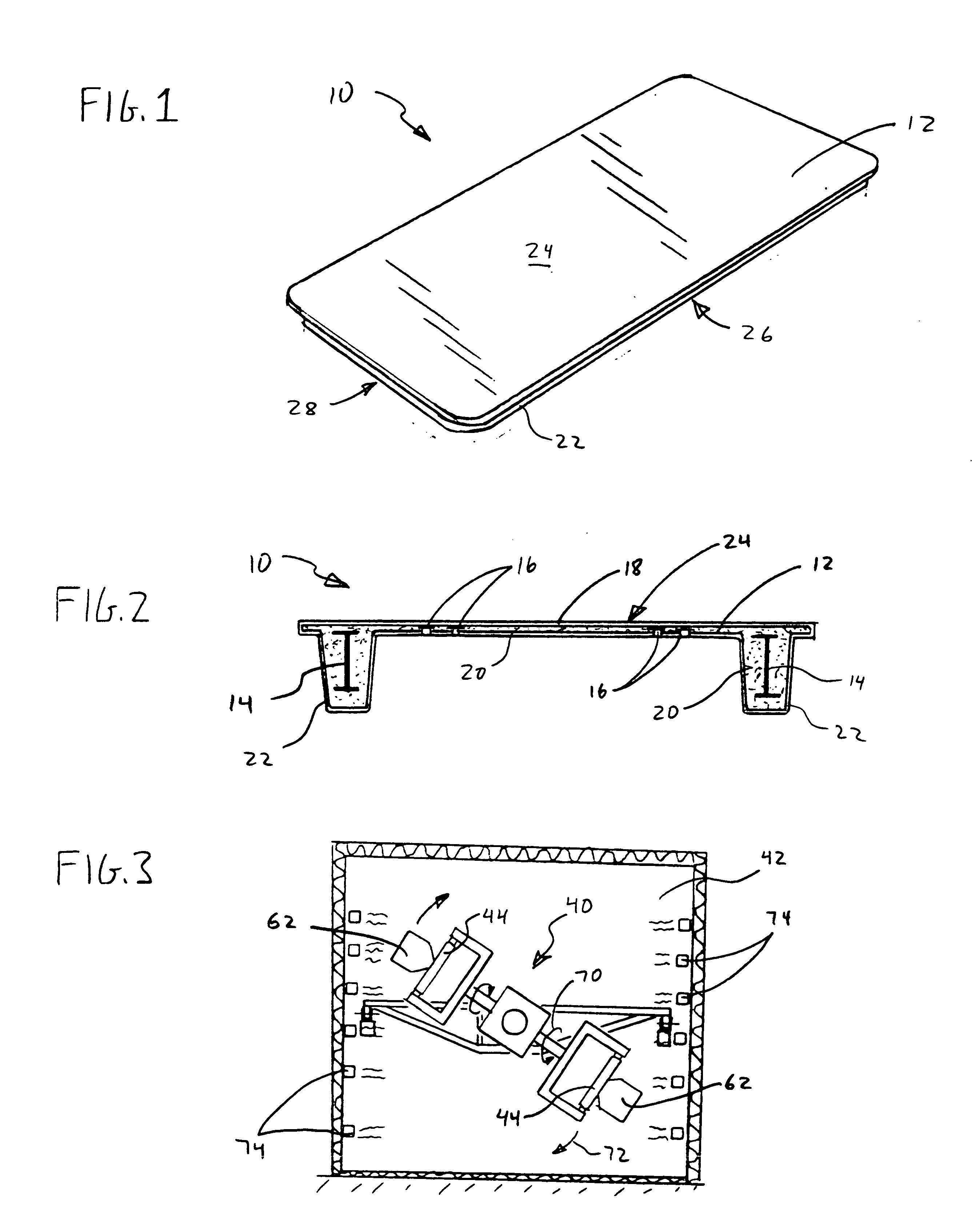
[0024] The present invention advantageously provides a molded article or structural member and a system and method for manufacturing the same. The system and method can be used to produce a wide variety of different molded articles in accordance with the invention. One example of such a molded article is a molded table 10 shown in FIGS. 1, 2, and 7. The table shown in these figures comprises a rotationally-mold...


PUM

PropertyMeasurementUnit
Shapeaaaaaaaaaa

Abstract

A molded article includes a rotationally-molded body of polymer material, formed in a mold, with an elongate reinforcing member, having an end, substantially encased within the body of polymer material during molding thereof. A slip zone, defining a void in the body of polymer material, is formed around the end of the reinforcing member, such that post-molding shrinkage of the polymer material imposes substantially no stress on the end of the reinforcing member.

Description

PRIORITY CLAIM [0001] The present application claims priority from U.S. Provisional Patent Application Ser. No. 60 / 529,006, filed on Dec. 12, 2003.BACKGROUND OF THE INVENTION [0002] 1. Field of the Invention [0003] The present invention relates generally to molded polymer articles. More particularly, the present invention relates to a molded polymer article with an expanded foam core and a reinforcing member encased within the foam core. [0004] 2. Related Art [0005] Polymer materials have come into use for the fabrication of lightweight articles, such as tables, risers, kayaks, etc. Some of these types of articles include plastic layers or grid frameworks as reinforcing members, with outer plastic layers in various forms. They may be fabricated by forming a skin, such as by blow molding, rotational molding, or vacuum forming to produce a plastic shell, with a frame disposed in the shell or connected to the exterior of the shell to add structural rigidity. In some cases, an expansive...

Claims


Application Information

Patent Timeline
IPC IPC(8): A23G3/34B29C31/00B29C33/12B29C37/00B29C41/06B29C41/20B29C41/36B29C70/68
CPCA23G3/0029A23G3/0042B29C31/008B29C33/123B29C37/0067B29L2031/448B29C41/20B29C41/36B29C70/683B29K2105/04B29C41/06Y10T428/249989Y10T428/249953
Inventor LAWS, R. DRULAWS, DAVID J.SWINDLER, PHILLIPOLSON, NICKCOLTON, KIP M.COLTON, NIKKI
Owner MITY-LITE
Learn More