
Delay based space and time coordinated repeater system

a repeater system and space and time coordination technology, applied in repeater circuits, line-transmission details, electromagnetical wave modulation, etc., can solve problems such as distortions that one would not want compounded, and achieve the effects of convenient mobile network, convenient multiple point-to-point communication links, and more economical utilization of hardware resources

Inactive Publication Date: 2005-06-16
SUBSCRIBER SOLUTIONS
View PDF8 Cites 23 Cited by
  • Summary
  • Abstract
  • Description
  • Claims
  • Application Information

AI Technical Summary

Benefits of technology

[0024] It is therefore an object of the present invention to provide a novel method of utilizing a dynamically configurable array of repeaters to facilitate multiple point-to-point communication links. It is a further object of the present invention to facilitate a mobile network who's capacity to handle calls grows automatically with the number of users in the system, such that overloads during high utilization times such drive time or at times of disaster do not occur. It is a further object of the present invention to provide more economical utilization of hardware resources in an array of repeaters to provide more economical multiple point-to-point communication links. It is a further object of the present invention to facilitate point-to-point communication between any two transceivers in a matrix of transceivers, with minimal or no reliance on ground (base) stations. It is a further object of the present invention to reduce the required transmitter power in an urban environment containing a plurality of mobile personal transceivers. It is a further object of the present invention to provide a novel method for enhanced-security military communication across or around select geographic areas.

Problems solved by technology

Heterodyning (mixing) is a nonlinear operation, it preserves the linearity of the signal, whereas techniques used to ultimately demodulate a signal to baseband usually result in distortion which one would not want compounded along a chain of repeaters.

Method used


Image

  • Delay based space and time coordinated repeater system
  • Delay based space and time coordinated repeater system
  • Delay based space and time coordinated repeater system

Examples


Embodiment Construction

[0037] As required, a detailed illustrative embodiment of the present invention is disclosed herein. However, techniques, systems and operating structures in accordance with the present invention may be embodied in a wide variety of forms and modes, some of which may be quite different from those in the disclosed embodiment. Consequently, the specific structural and functional details disclosed herein are merely representative, yet in that regard, they are deemed to afford the best embodiment for purposes of disclosure and to provide a basis for the claims herein which define the scope of the present invention. The following presents a detailed description of the preferred embodiment (as well as some alternative embodiments) of the present invention.

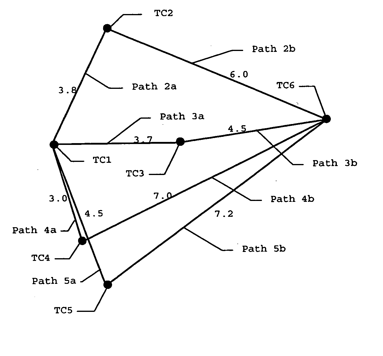
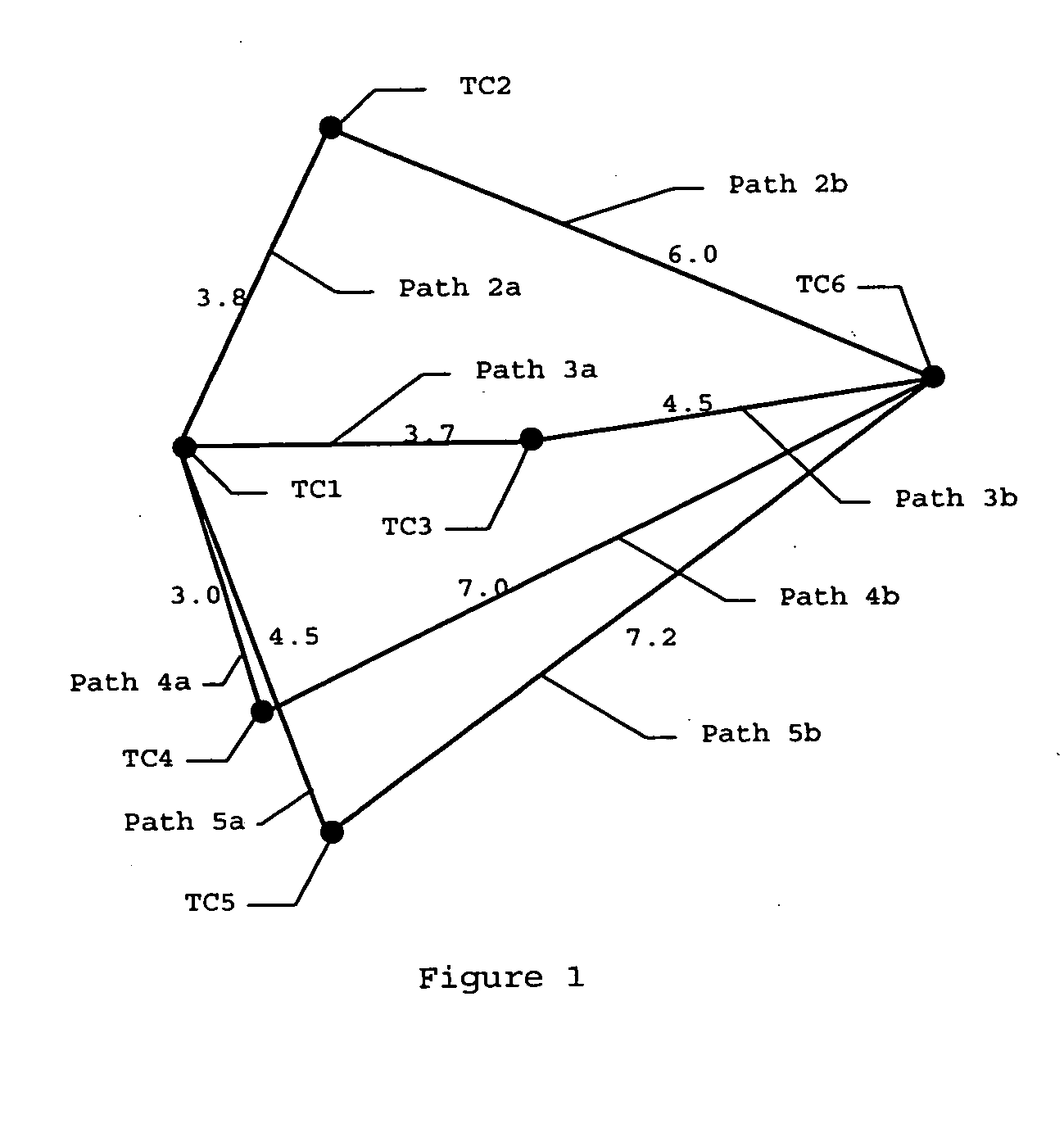
[0038] Referring first to FIG. 1, depicted is the spatial arrangement between 6 transceivers TC1-TC6, and the multiple paths that a signal takes through multiple repeaters in traveling from transceiver TC1 to transceiver TC6 in the pref...


PUM


Abstract

A method and apparatus are provided for dynamically routing a plurality of simultaneous point-to-point communications through an array of repeating transceivers. Each repeating transceiver may simultaneously act as each of a transmitter of origin for one communication, a final receiver for a second communication, and a repeater for a plurality of other communications. When acting as a repeater, each transceiver applies programmed delays to information before re-transmitting, and these delays are programmed so as to route a communication through the array of transceivers along a designed path along which multiple re-transmissions from local repeating transceivers are received, aligned in time for constructive reinforcement, and retransmitted after dynamically programmable time delays.

Description

FIELD OF THE INVENTION [0001] The field of the invention relates to Radio communications, and more particularly to synthetic aperture antenna systems and tapped-delay-line signal enhancement techniques. More specifically, the invention relates to a method and apparatus for utilizing a dynamically configured array of repeaters to facilitate multiple point-to-point communication links. BACKGROUND OF THE INVENTION [0002] Ever since radio transmission first became a reality, utilization of the electromagnetic (EM) spectrum for communication has continued to grow. Every part of the electromagnetic spectrum from AM radio up through infrared and visible light is now used to transmit information. Modern consumer devices which transmit and / or receive EM signals include FM and AM radios, CB and personal radios, televisions, pagers, cell phones, remote controls for consumer electronics, GPS receivers, PDAs, cordless phones, wireless local area networks, wireless computer peripherals, garage do...

Claims


Application Information

Patent Timeline
Patent Type & Authority Applications(United States)
IPC IPC(8): H04B7/15
CPCH04B7/155
Inventor PRATT, GILLREED, DAVID PATRICK
Owner SUBSCRIBER SOLUTIONS
Features
  • Generate Ideas
  • Intellectual Property
  • Life Sciences
  • Materials
  • Tech Scout
  • Unparalleled Data Quality
  • Higher Quality Content
  • 60% Fewer Hallucinations
Learn More