
Self-tuning variable impedance circuit for impedance matching of power amplifiers

a technology of impedance matching and variable impedance, which is applied in the direction of amplifiers with semiconductor devices/discharge tubes, gain control, transmission, etc., can solve the problems of less than optimal efficiency at lower power, inability to straightforwardly reduce the consumption of amplifiers, and add complexity, so as to reduce the capacitance of voltage-variable capacitors and increase the power efficiency. , the effect of reducing the impedance of the impedance matching circui

Active Publication Date: 2005-06-16
QORVO US INC
View PDF6 Cites 103 Cited by
  • Summary
  • Abstract
  • Description
  • Claims
  • Application Information

AI Technical Summary

Benefits of technology

[0010] For example, the variable impedance circuit can be designed to automatically “follow” the output power of a power amplifier, thereby increasing its power efficiency. In one approach, an increase in output power or applied voltage causes a decrease in capacitance of the voltage-variable capacitor or a decrease in the impedance of the impedance matching circuit, resulting in better matching and improved power efficiency of the power amplifier. In some cases, the matching that is achieved by self-tuning may not result in the maximum possible matching and may be augmented by a control circuit that actively tunes the impedance matching circuit to further improve the matching.

Problems solved by technology

However, if a power amplifier is required to boost signal power by a certain amount, the amplifier's consumption cannot be straightforwardly reduced simply by feeding less power to the amplifier.
However, this results in less than optimal efficiency at lower powers.
However, this approach requires a control algorithm, which adds complexity.
It also requires additional control circuitry, which adds to the overall power consumption.
This approach has the drawbacks of both of the previous approaches.
It also is not optimal for many output powers since, for example, neither load impedance will be optimal for intermediate output powers.

Method used


Image

  • Self-tuning variable impedance circuit for impedance matching of power amplifiers
  • Self-tuning variable impedance circuit for impedance matching of power amplifiers
  • Self-tuning variable impedance circuit for impedance matching of power amplifiers

Examples


Embodiment Construction

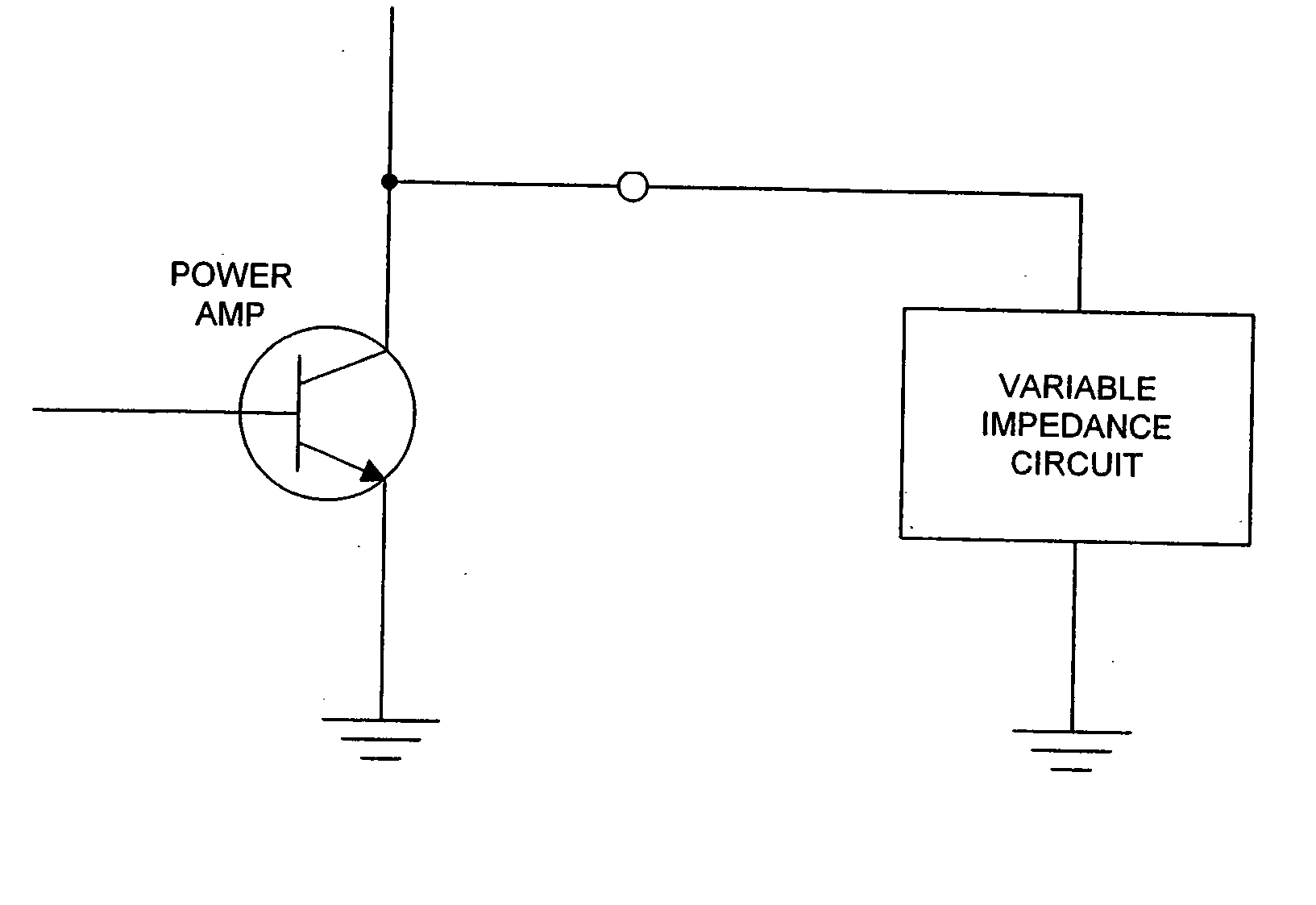
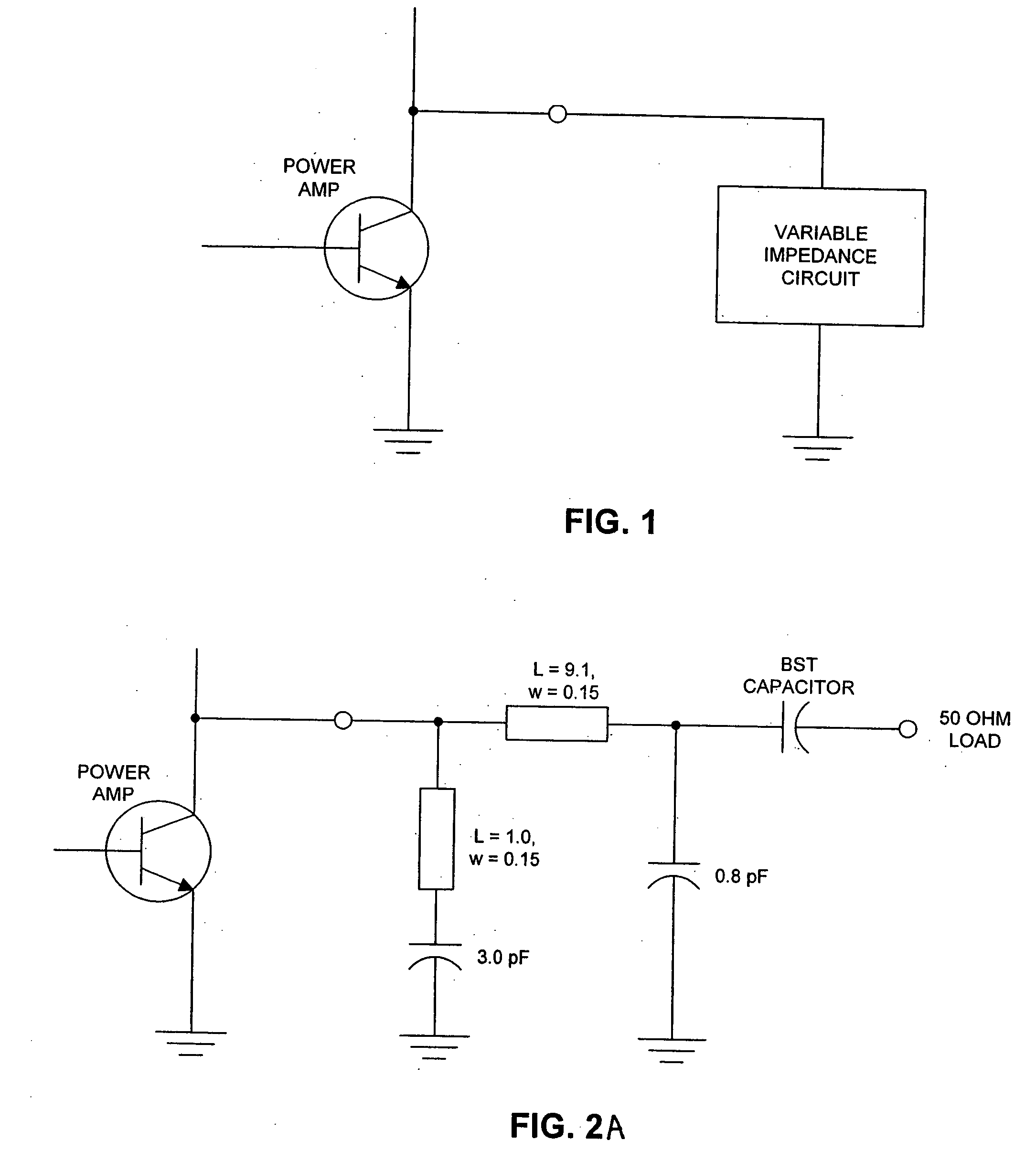
[0026]FIG. 1 shows a power amplifier coupled to a variable impedance circuit that is used for impedance matching the power amplifier. The impedance matching circuit includes a self-tuning voltage-variable capacitor. As a result, the impedance of the circuit is variable and self-tunes, as described below, to match the power amplifier.

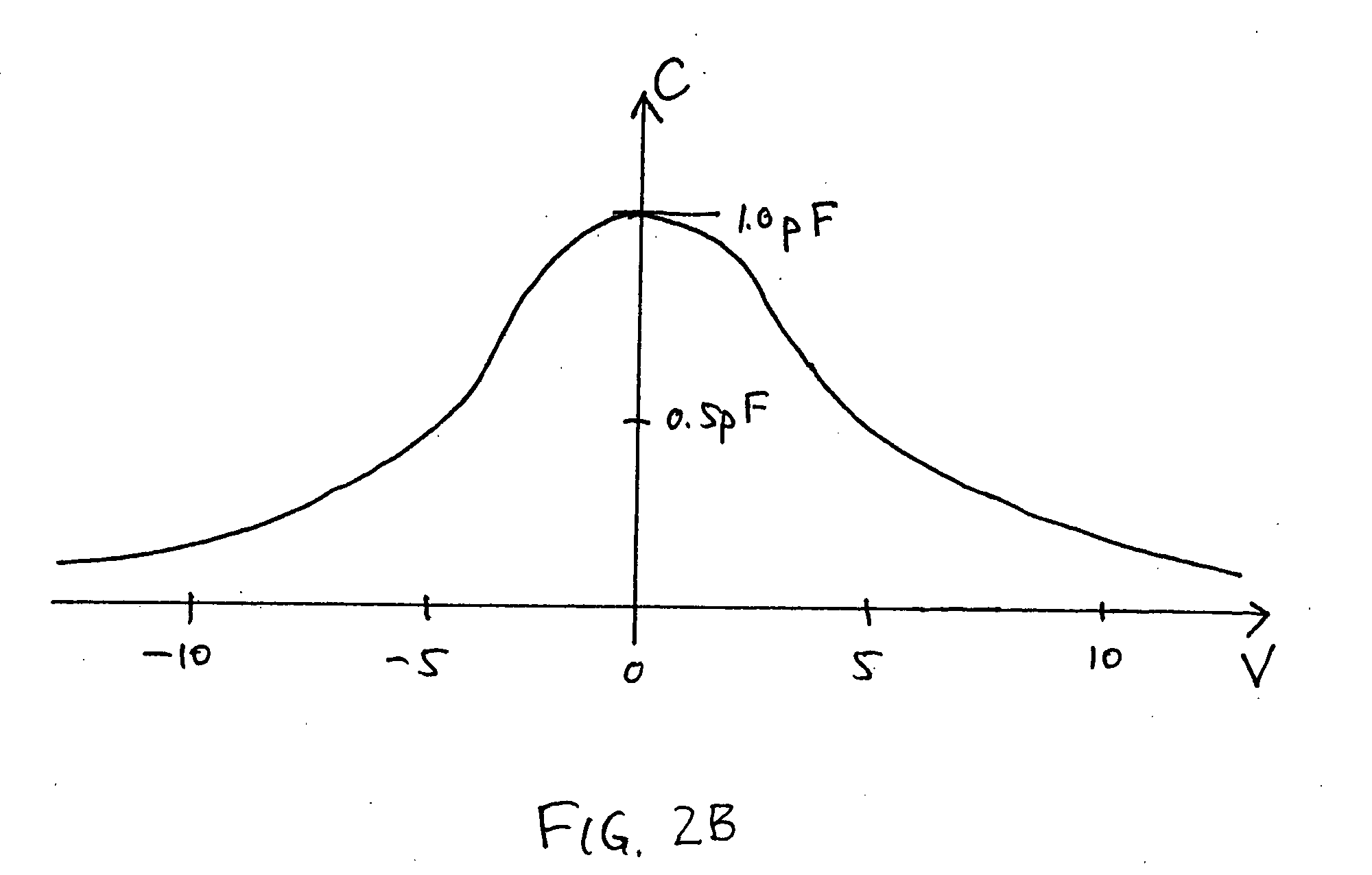
[0027] The power applied across the capacitor induces a change in the capacitance of the voltage-variable capacitor. The impedance matching circuit is designed so that, when the power amplifier has a high output power, the voltage-variable capacitor has a capacitance that makes the overall impedance of the circuit low, thus matching the power amplifier. When the power amplifier has a low output power, the voltage-variable capacitor has a capacitance that results in high overall impedance for the circuit, again matching the power amplifier. As the output power of the amplifier varies between low and high, the capacitance automatically varies in a corresp...


PUM


Abstract

A self-tuning variable impedance circuit provides improved performance. A variation in the power applied to the variable impedance circuit causes a corresponding change in the impedance of the circuit, resulting in improved performance. For example, the variable impedance circuit may be a matching circuit that “follows” the output power of a power amplifier, thereby increasing the power efficiency of the power amplifier.

Description

CROSS-REFERENCE TO RELATED APPLICATION [0001] This application claims priority under 35 U.S.C. § 119(e) to U.S. Provisional Patent Application Ser. No. 60 / 493,031, “Self-Tuning Variable Impedance Circuit for Impedance Matching of Power Amplifiers,” filed Aug. 5, 2003 by Roger J. Forse. The subject matter of the foregoing is incorporated herein by reference in its entirety.BACKGROUND OF THE INVENTION [0002] 1. Field of the Invention [0003] This invention relates generally to self-tuning variable impedance circuits, for example as may be used for impedance matching of power amplifiers. [0004] 2. Description of the Related Art [0005] Power amplifiers are a commonly used component in many types of systems. For example, the recent increase in wireless systems (e.g., the cellular phone network) has resulted in a corresponding increase in wireless handsets. Within these handsets, power amplifiers are commonly used to boost signal powers and can account for a significant fraction of the ove...

Claims


Application Information

Patent Timeline
IPC IPC(8): H03F1/56H03F3/191H04B1/04
CPCH03F1/56H04B1/0458H03F3/191
Inventor FORSE, ROGER J.CHEN, VICKIYORK, ROBERT A.CHASE, DAVID R.
Owner QORVO US INC
Learn More