Ultrasonic probe having a selector switch

Inactive Publication Date: 2005-06-16
KONINKLIJKE PHILIPS ELECTRONICS NV
View PDF20 Cites 85 Cited by
  • Summary
  • Abstract
  • Description
  • Claims
  • Application Information

AI Technical Summary

Benefits of technology

[0017] An ultrasonic transducer probe having a selector switch and controls built in for controlling imaging processes utilizing multidimensional transducer array technology and/or microbeamforming, thereby controlling the characteristics of the acquired ultrasonic image is hereinafter disclosed. In particular, the apparatus includes a housing, an ultrasonic probe having an ultrasonic transducer assembly, user controls which may include a selector switch having at least two user-selectable positions or states, and/or a positional device, and associated circuitry. The ultrasonic transducer assembly includes a plurality of acoustic elements configured and arranged in a multidimensional array, which is designed to fit within the housing of the ultrasonic probe. Each of the acoustic elements in the multidimensional transducer array is capable of generating an acoustic pulse and/or receiving an echo signal, and is controlled using microbeamforming technology. That is, a microbeamformer is coupled to the array and drives the acoustic elements included in the multidimensional array. The operation of the array is controllable via the probe handle controls, which select the imaging modes and scanning parameters of the system. The microbeamformer further includes associated circuitry capable of controlling the placement of acoustic transmit and receive beams by generating control signals in cooperation with a provided user interface, thereby controlling the acquired field of view. The associated circuitry of the ultrasonic probe may provide that the microbeamformer generates and controls the acoustic beam in accordance with at least one of the at least two user-selectable states. A signal processor is coupled to the array for processing at least one echo signal to form at least one image signal. A display operatively coupled to the signal processor is further included for displaying data corresponding to the at least one image signal. A storage device may be provided for storing and/or retrieving data corresponding to the at least one image signal. A communication device may be provided for transferring image data and associated d

Problems solved by technology

By employing the aforementioned technique of receive parallelism, fewer scan lines may be utilized to generate an image, thereby desirably increasing frame rate.
In newer transducers, especially those that include multi-dimensional arrays, comprising hundreds or thousands of acoustic elements, the task of driving transmit pulses to large numbers of elements, and the corresponding task of dynamically beamforming the receive signals from large numbers of elements makes for prohibitively complex and expensive beamformers.
Transducer probes which employ one-dimensional arrays of acoustic elements are generally limited to steering scan lines in a single plane.
Nevertheless, such probes share the same limit

Method used


Image

  • Ultrasonic probe having a selector switch
  • Ultrasonic probe having a selector switch
  • Ultrasonic probe having a selector switch

Examples


Embodiment Construction

[0025] Several embodiments of the present invention are hereby disclosed in the accompanying description in conjunction with the figures. Preferred embodiments of the present invention will now be described in detail with reference to the figures wherein like reference numerals identify similar or identical elements.

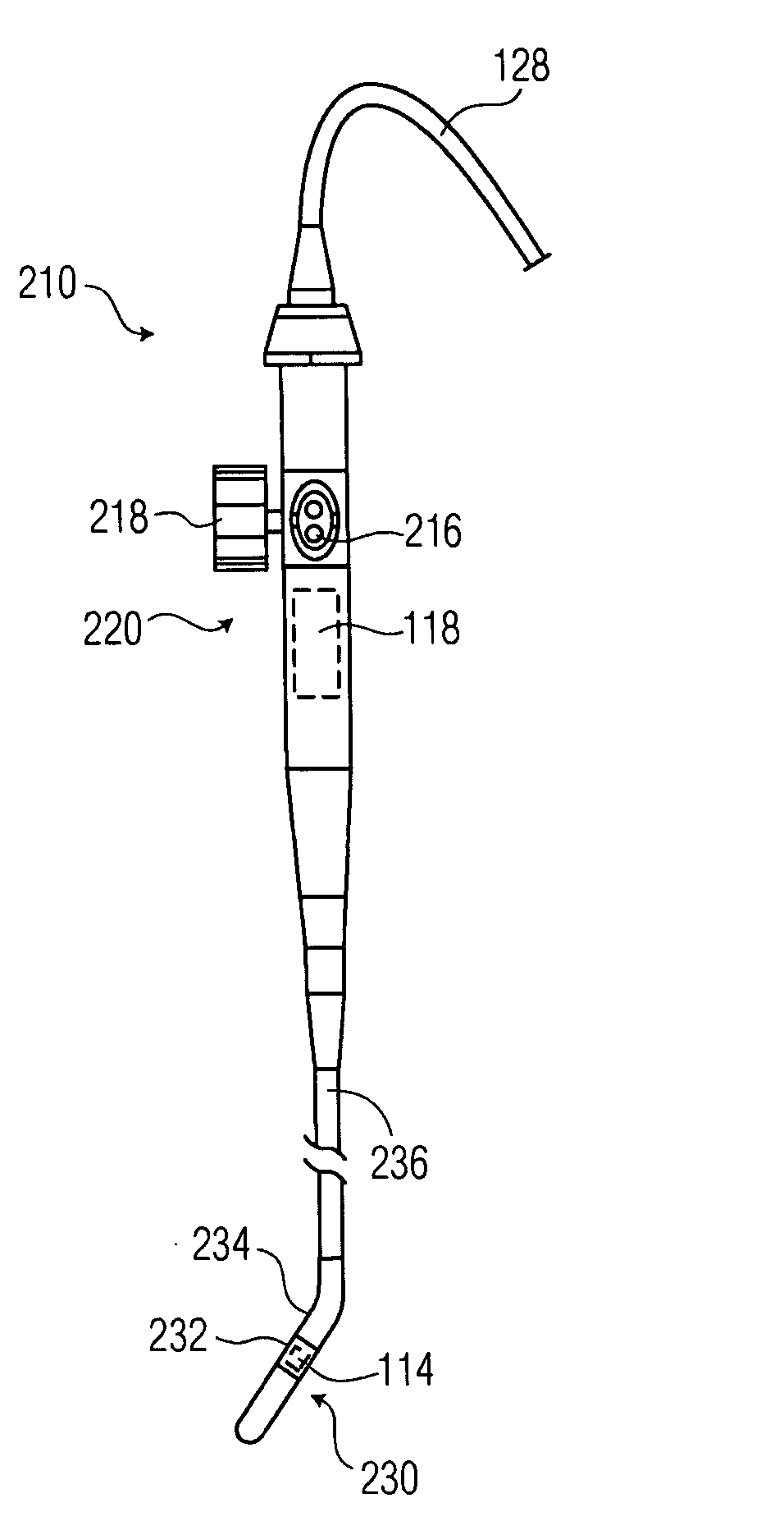
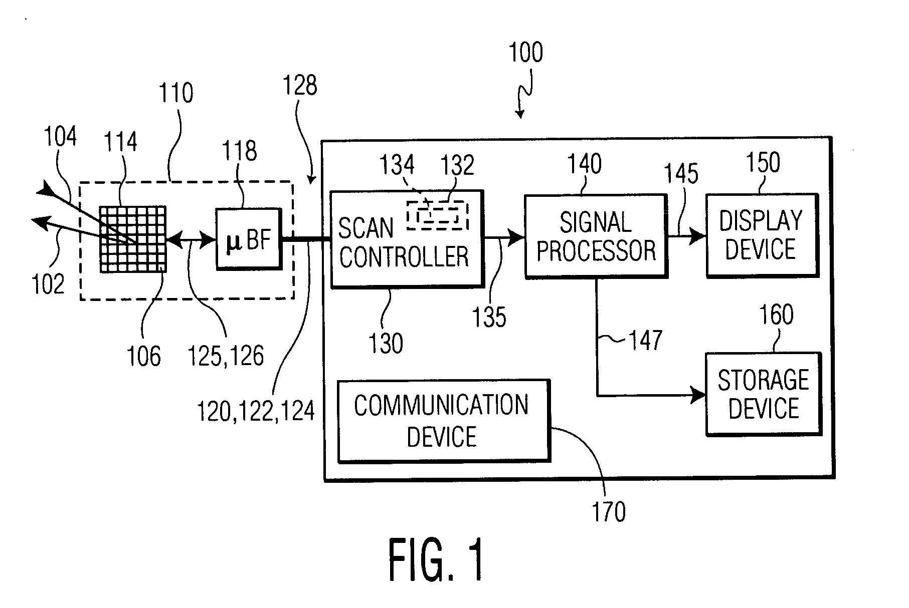
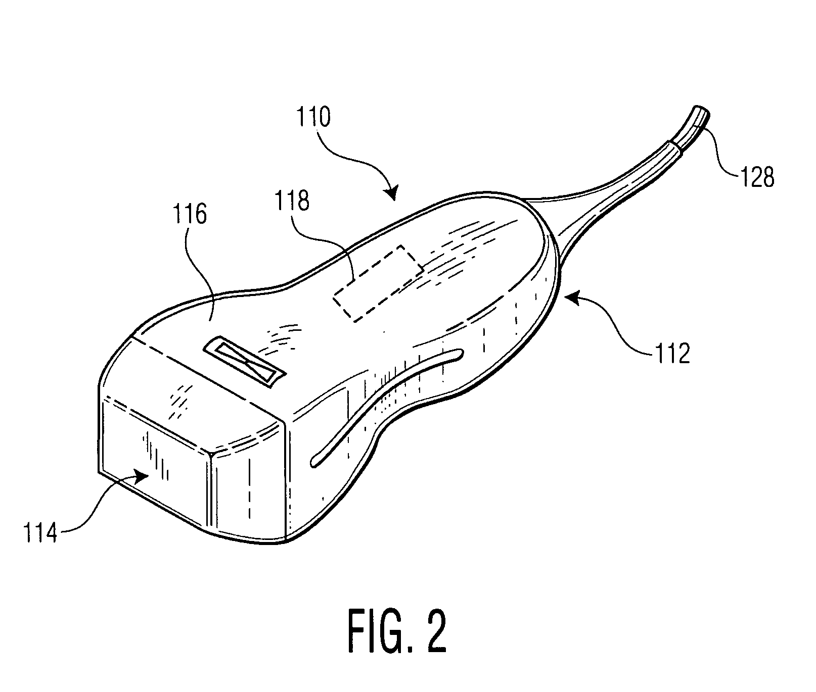
[0026] An ultrasonic imaging system according to the present invention is illustrated in FIG. 1, and further described with specificity hereinafter. The ultrasonic imaging system 100 includes an ultrasonic probe 110 having a housing 112 (FIG. 2), an ultrasonic transducer assembly 114, a selector switch 116 (FIG. 2), and a microbeamformer 118 (shown in phantom in FIGS. 2-3).

[0027] The ultrasonic transducer assembly 114 includes a plurality of acoustic elements 106 arranged in a number of columns and rows for generating at least one acoustic transmit beam 102 and / or receiving echoes from at least one receive beam 104. While the beams 102 and 104 are shown in the figure t...


PUM


Abstract

An ultrasonic probe having a selector switch and a housing is provided. The ultrasonic probe further includes an ultrasonic transducer assembly and associated circuitry. A beamformer may be included in the ultrasonic probe. The selector switch has at least two user-selectable positions or states. The selector switch and the associated circuitry control an output acoustic beam of the ultrasonic imaging apparatus in accordance with the user-selectable position or state.

Description

CROSS REFERENCE TO RELATED CASES [0001] Applicant claims the benefit of Provisional Application Ser. No. 60 / 529,787, filed 16 Dec. 2003, and Provisional Application Ser. No. 60 / 615,426, filed 1 Oct. 2004.BACKGROUND OF THE INVENTION [0002] 1. Field of the Invention [0003] The present invention relates generally to ultrasonic imaging systems. More particularly, it relates to ultrasonic imaging systems with an ultrasonic probe having a selector switch for controlling characteristics of the acquired ultrasonic image. [0004] 2. Description of the Related Art [0005] Ultrasonic transducer probes transmit and receive ultrasound energy in any diagnostic ultrasound medical imaging system. Ultrasound medical imaging systems are used in many medical applications and, in particular, for the non-invasive acquisition of images of organs and conditions within a patient, e.g., fetuses, the heart. Ultrasonic transducer probes are generally hand held, but vary significantly in accordance with their in...

Claims


Application Information

Patent Timeline
IPC IPC(8): A61B8/00G01N29/24A61B8/14
CPCA61B8/14G01S7/52084G01S15/8915G01S15/8927G01S7/5208
Inventor POLAND, MCKEE D.
Owner KONINKLIJKE PHILIPS ELECTRONICS NV
Why Eureka
Try Eureka