Gas turbine engine architecture

a technology for gas turbine engines and engine structures, applied in engine lubrication, jet propulsion plants, air transportation, etc., can solve the problems of increased cost, weight and complexity of engine design, and achieve the effect of improving the architectur

Active Publication Date: 2005-06-23
PRATT & WHITNEY CANADA CORP
View PDF15 Cites 43 Cited by
  • Summary
  • Abstract
  • Description
  • Claims
  • Application Information

AI Technical Summary

Benefits of technology

[0003] It is an object of the present invention to provide a gas turbine engine having an improved architecture.

Problems solved by technology

The greater the number of oil cavities required, the greater the cost, weight and complexity of the engine design.

Method used


Image

  • Gas turbine engine architecture
  • Gas turbine engine architecture
  • Gas turbine engine architecture

Examples


Embodiment Construction

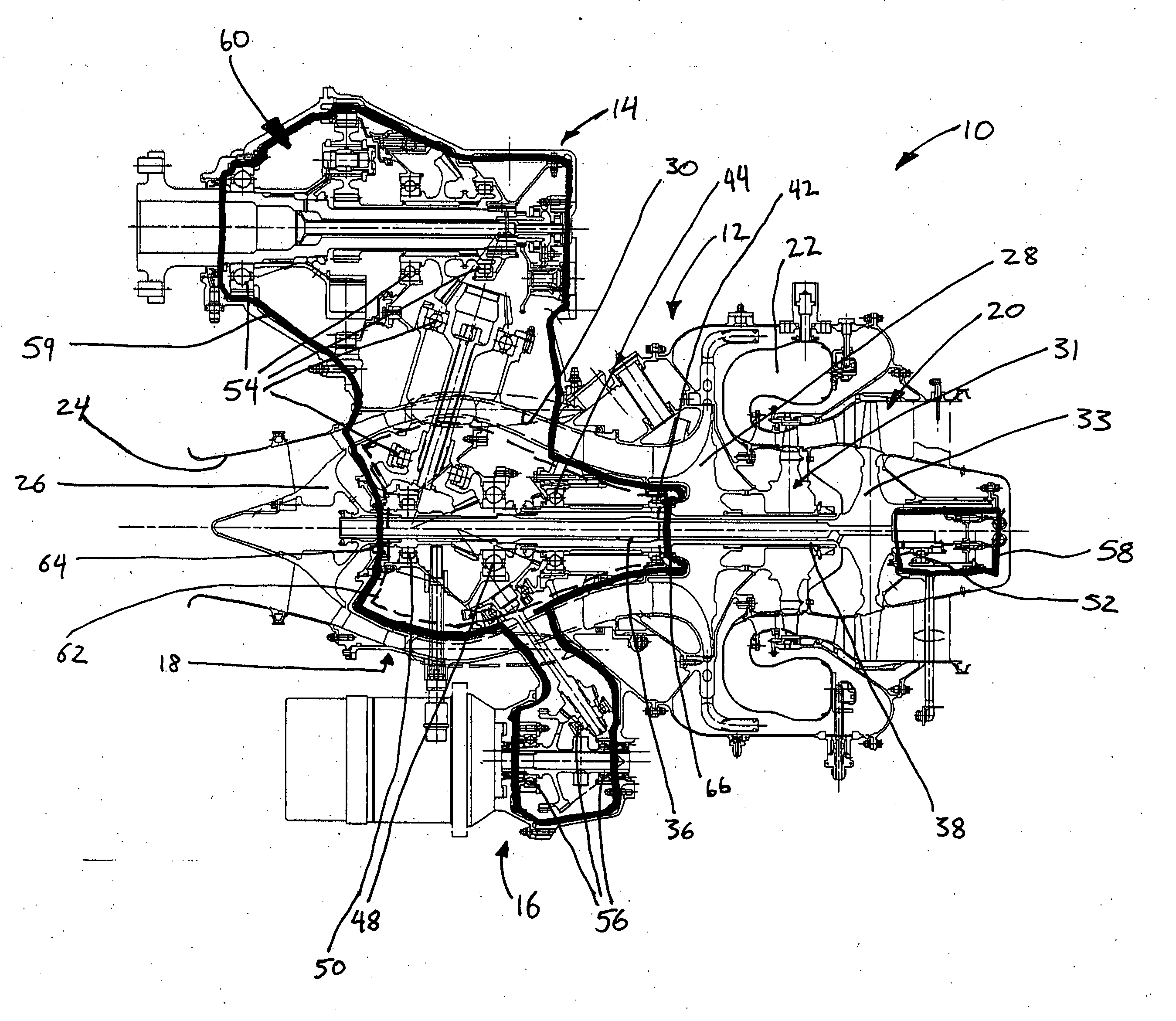
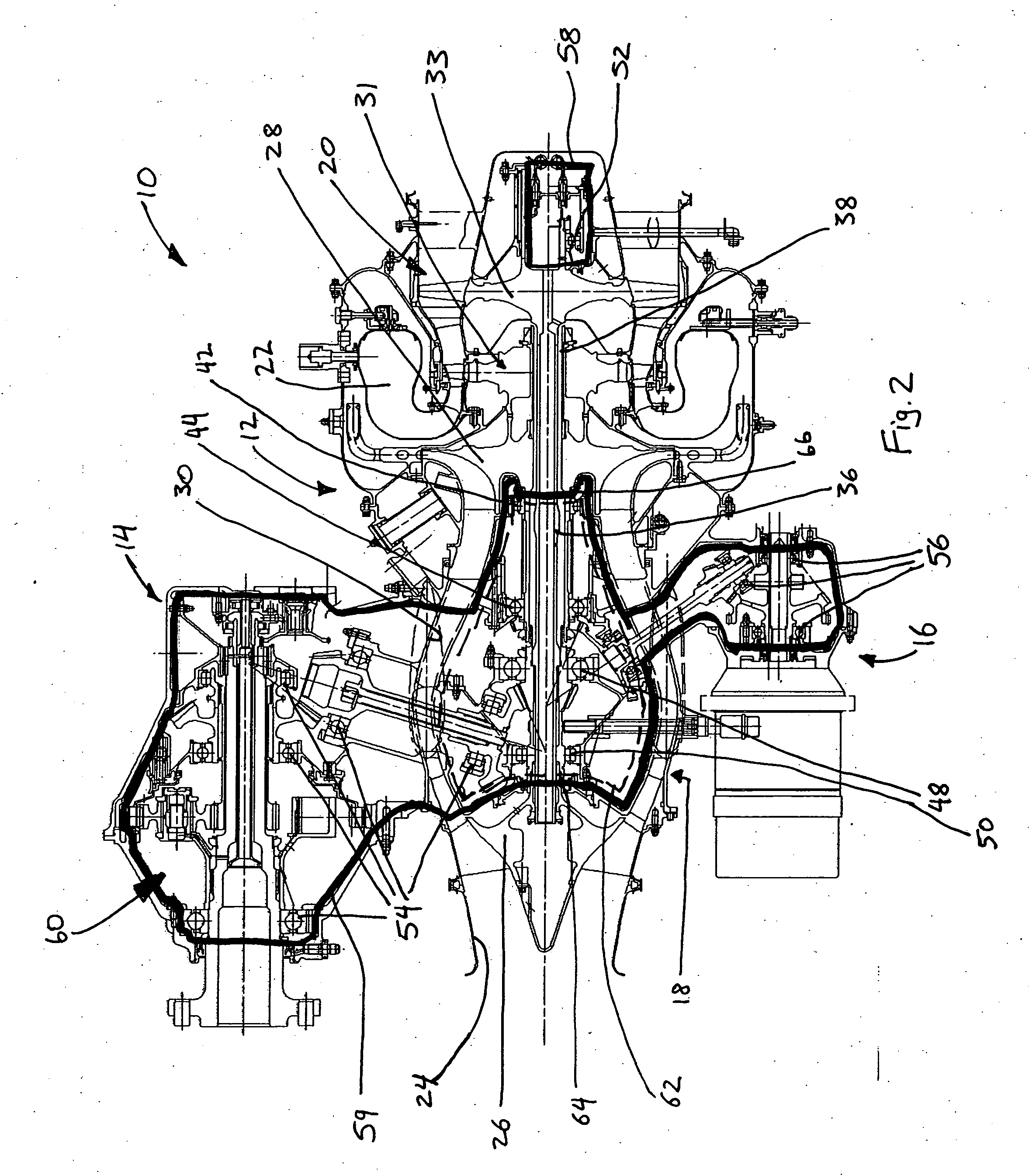
[0011] Referring to FIG. 2, the gas turbine engine 10 of the present invention is of a type preferably provided for use in subsonic flight and generally described in U.S. patent application Publication No. US2003 / 0115885 (incorporated herein by reference). The gas turbine engine 10 generally comprises a gas generator module 12 including, in serial flow communication, a multistage compressor portion 18 for pressurizing the air, a combustor portion 22 in which the compressed air is mixed with fuel and ignited for generating an annular stream of hot combustion gases, and a turbine portion 20 for extracting energy from the combustion gases.

[0012] The compressor portion 18 includes an air inlet 24, a booster stage or boosted rotor type low pressure (LP) compressor 26 (which may be of the type described in U.S. Pat. No. 6,488,469, incorporated herein by reference), and a centrifugal impeller type high pressure (HP) compressor 28 at the outlet end of a compressor air flow duct 30.

[0013] ...


PUM


Abstract

A gas turbine engine having an oil cavity architecture and bearing placement which reduce heat rejection and oil system complexity by enclosing the reduction gearbox bearings and at least the shaft bearings supporting the high pressure shaft in the same oil cavity.

Description

TECHNICAL FIELD [0001] The present invention relates generally gas turbine engines, and more particularly to an improved architecture for a gas turbine engine. BACKGROUND OF THE INVENTION [0002] Traditional gas turbine engine layouts necessitate a plurality of oil lubricated bearings spaced apart throughout the engine, and hence require a plurality of oil cavities which contain and feed oil to these bearings. The greater the number of oil cavities required, the greater the cost, weight and complexity of the engine design. Additionally, more oil cavities increases the possibility of potential oil leakages associated with external pipes used to transfer oil to and between the various spaced apart bearing cavities. FIG. 1 illustrates such a typical gas turbine engine layout having six bearing cavities, generally identified as A through F, each of which may comprise several individual bearings therewithin. SUMMARY OF THE INVENTION [0003] It is an object of the present invention to provi...

Claims


Application Information

Patent Timeline
Patent Type & Authority Applications(United States)
IPC IPC(8): F02C7/06F02C7/36
CPCF01D25/18Y02T50/671F02C7/36F02C7/06Y02T50/60
Inventor MACFARLANE, IANSZLANTA, ZENONMITROVIC, LAZARMORGAN, KEITH
Owner PRATT & WHITNEY CANADA CORP
Why Eureka
Try Eureka