

Bifurcated oil scavenge system for a gas turbine engine
a gas turbine engine and scavenging system technology, applied in the direction of engines, machines/engines, mechanical equipment, etc., can solve the problems of increased oil leakage potential, increased oil leakage from the compartment, and disadvantages of conventional scavenging port arrangements
- Summary
- Abstract
- Description
- Claims
- Application Information
AI Technical Summary
Benefits of technology
Problems solved by technology
Method used
Image

Examples
Embodiment Construction
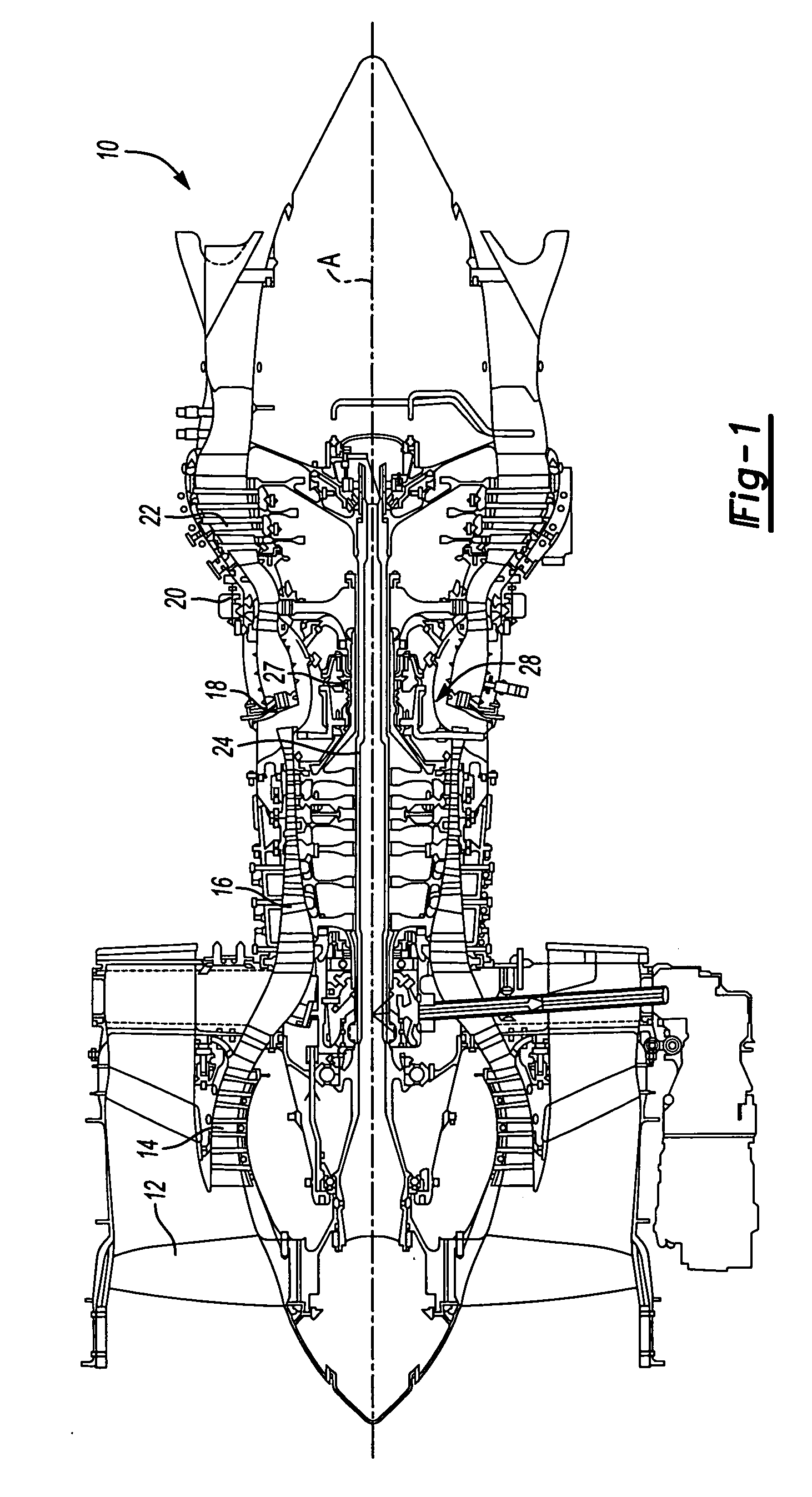
[0019]FIG. 1 illustrates a general schematic sectional view of a gas turbine engine 10.
[0020] The gas turbine engine 10 is defined about an engine centerline A about which the various engine sections rotate. Generally, the engine 10 includes a fan section 12, a low pressure compressor section 14, a high pressure compressor section 16, a combustor section 18, a high pressure turbine section 20 and a low pressure turbine section 22. It should be understood that although a particular arrangement is disclosed in the illustrated embodiment, other arrangements will benefit from the instant invention.
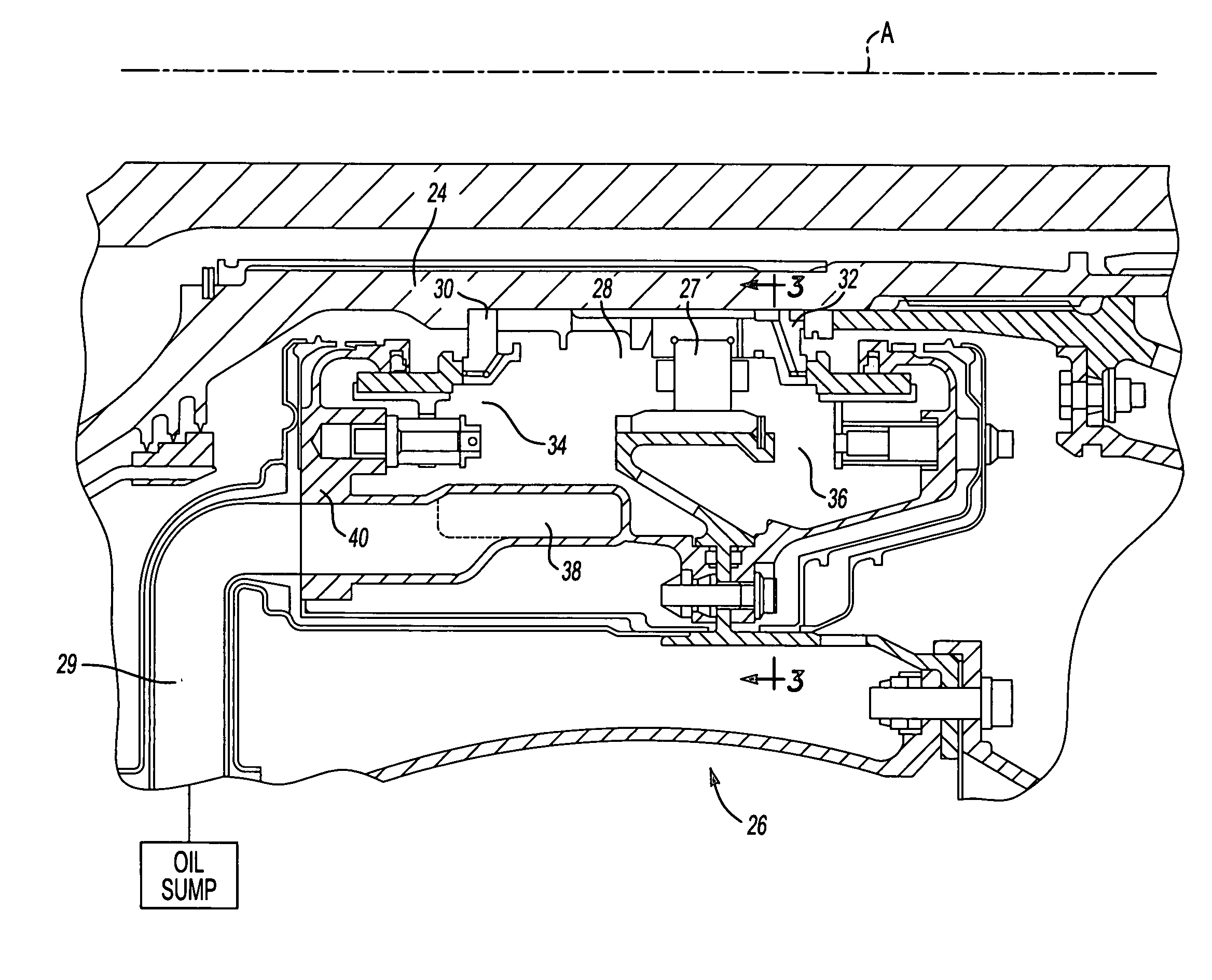
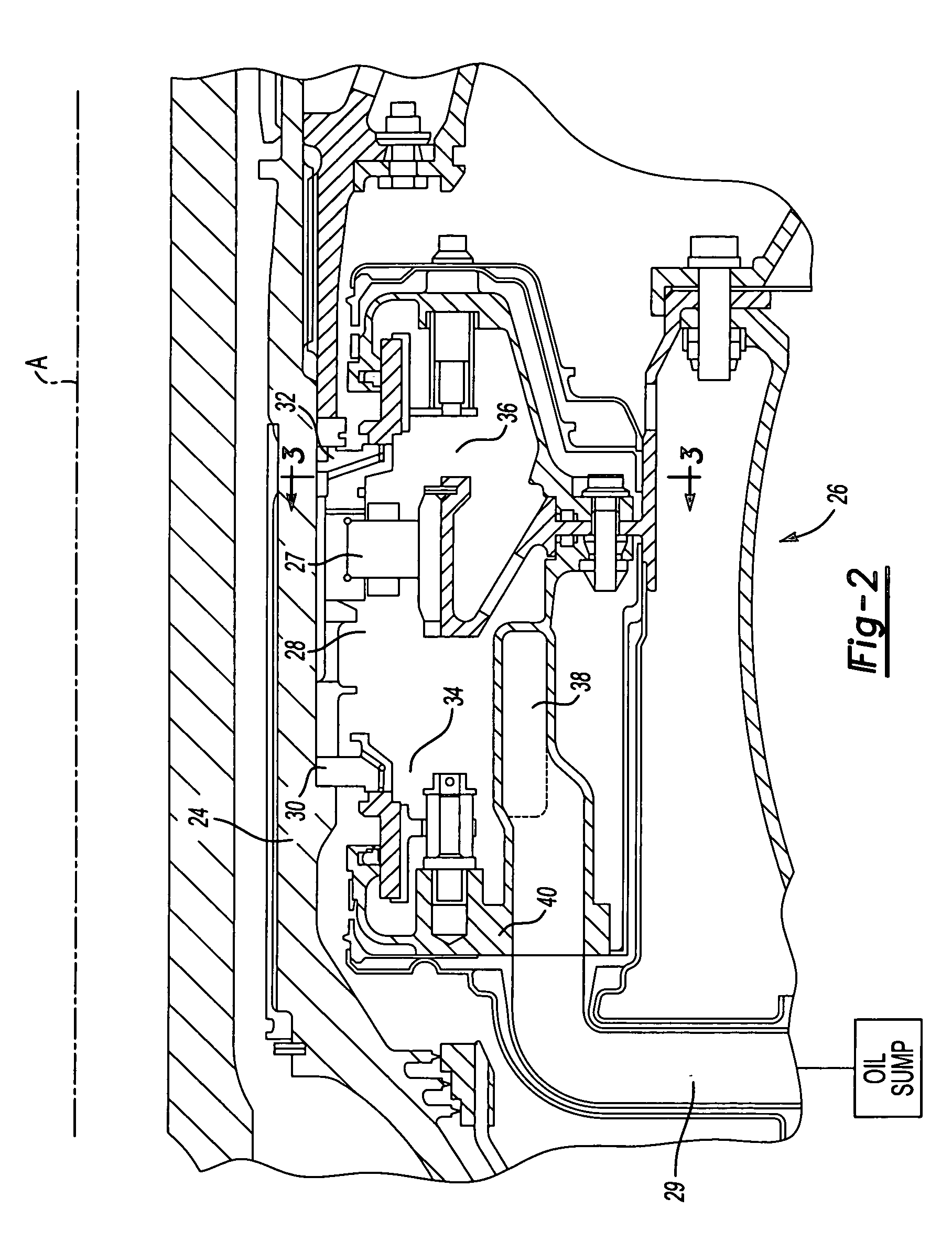
[0021] The sections are mounted about a main shaft 24 supported by various high speed bearings. One bearing 27 is located within a mid bearing compartment 28. The bearing 27 and compartment 28 receives lubrication and cooling from oil which is provided through jets and is then collected through an oil scavenge system which returns the oil to an oil sump through a flow path 29 (FIG. 2). It sh...
PUM
 Abstract
Description
Claims
Application Information