Yarn feeder

Inactive Publication Date: 2005-06-23
HIDEYUKI HAYASHI +1
View PDF5 Cites 2 Cited by
  • Summary
  • Abstract
  • Description
  • Claims
  • Application Information

AI Technical Summary

Benefits of technology

[0009] By individually applying braking force to selected pile yarns, the feed rates of the yarns can be freely changed without increasing the size or complicating the structure of the yarn feeder.
[0010] The brake device preferably comprises a grooved member formed with a plurality of grooves each for receiving one of the pile yarns, and a plurality of presser members which are individually movable toward the respective grooves until pressed against the bottoms with the pile yarns sandwiched between the presser members and the bottoms of the grooves, and movable away from the bottoms. Such a brake device is simpler in structure.
[0011] More preferably, the brake device comprises a plurality of brake units arranged in the feed direction of the pile yarns between the feed rolls and the needles, each of the brake units comprising a grooved member formed with a plurality of grooves each for receiving one of part of the pile yarns that are not fed through the other brake unit, and a plurality of presser members which are individually movable toward the bottoms of the respective grooves until pressed against the bottoms with the pile yarns sandwiched between the presser members and the bottoms of the grooves, and movable away from the bottoms. With this arrangement, pile yarns can be separately fed to the plurality of brake units which are arranged in the feed direction of the yarns. This minimizes the width of the yarn feeder and thus the entire tufting machine.
[0012] More preferably, the grooved member is a grooved roll which can be rotated at a variable speed and formed with a plurality of annular grooves formed in the outer peripheral surface the grooved roll, and the plurality of presser members are rotatably supported disks each having its outer edge received in one of the annular grooves so as to be individually pressed against the bottoms of the annular grooves with the pile yarns sandwiched therebetween. With this arrangement, by changing the rotational speed of the grooved roll, the feed rate of each yarn can be changed infinitely while the yarn is being braked. Thus, pile heights can be changed infinitely, which of course greatly increases the variation of pile patterns.

Problems solved by technology

For the above reasons, the yarn feeders disclosed in these prior publications are complicated in structure and expensive.
This of course requires large space in which the plate members can swing, which in turn increases the size of the yarn feeder and thus the entire tufting machine.
Moreover, pile yarns passed through holes formed in any particular plate member cannot be pulled out of this particular plate member and inserted into another plate member while the tufting machine is in operation.

Method used


Image

  • Yarn feeder
  • Yarn feeder
  • Yarn feeder

Examples


Embodiment Construction

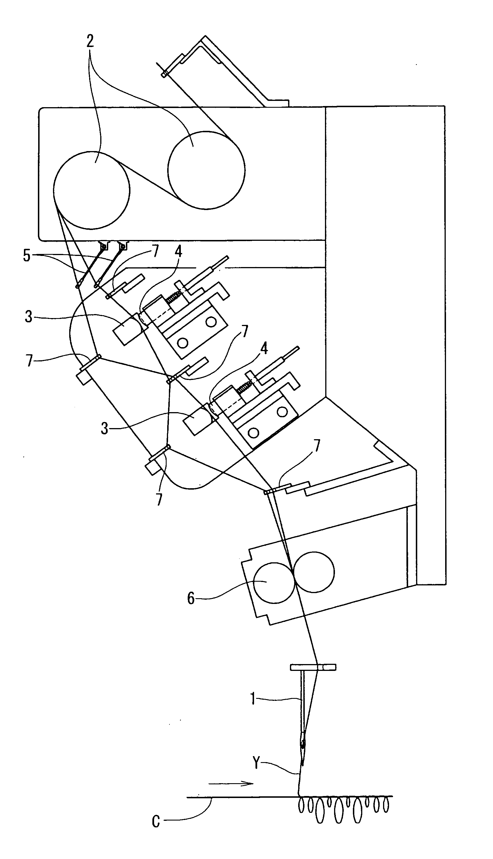
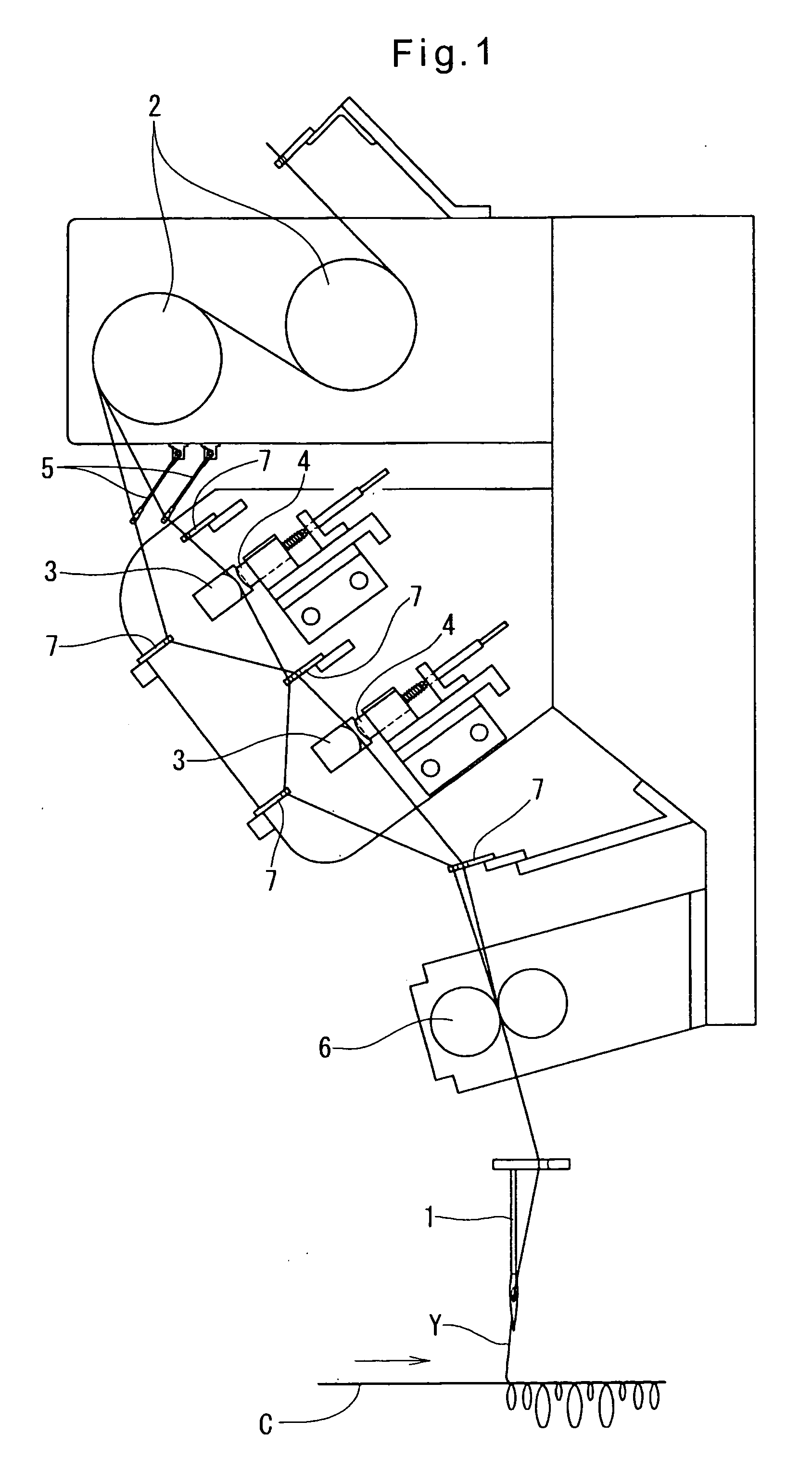
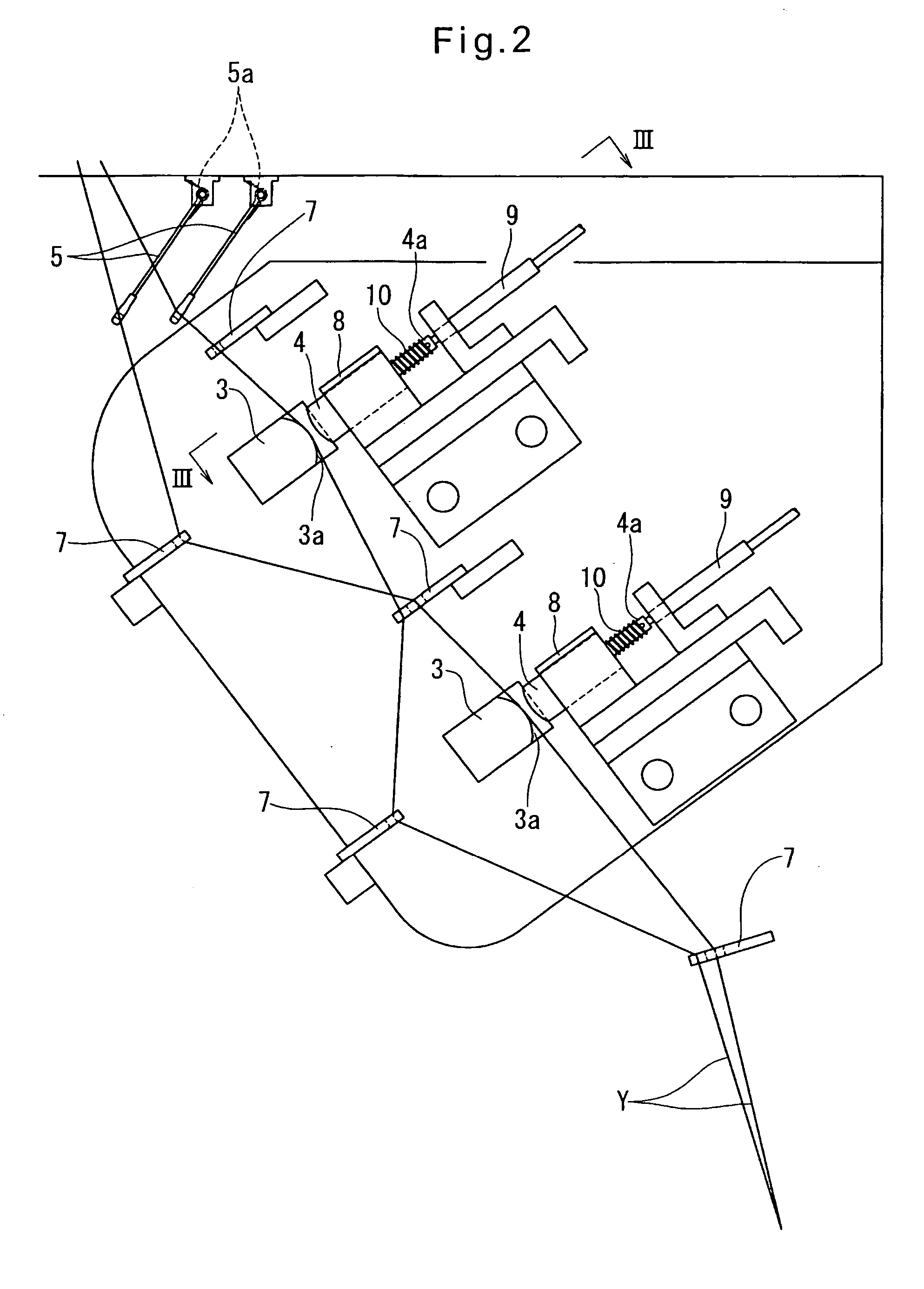
[0021] Referring now to FIGS. 1-4, the yarn feeder for use in a tufting machine according to the first embodiment of the present invention includes feed rolls 2 (FIG. 1) for feeding pile yarns Y at a predetermined speed to respective needles 1 of the tufting machine that are aligned in the width direction of a fabric C to be formed into a tufted carpet. While being fed between the feed rolls 2 and the needles 1, the pile yarns Y pass through a brake means which can individually apply braking force to the respective yarns. As shown in FIGS. 2 and 3, the brake means comprises two brake units each comprising a plate member 3 having parallel grooves 3a formed in the top surface thereof at equal intervals in the width direction thereof, and a plurality of presser members 4 which can be inserted into the respective grooves 3a. Between the feed rolls 2 and each of the brake units, each yarn Y is engaged by a swing arm 5 biased by a torsion coil spring 5a in a direction to apply tension to ...


PUM


Abstract

A yarn feeder for a tufting machine which is compact and simple in structure and is still capable of freely changing the heights of piles formed by each pile yarn on a fabric. The yarn feeder includes yarn feed rolls for feeding pile yarns to a row of needles of the tufting machine, and a brake device provided between the feed rolls and the needles. The brake device includes a grooved plate having grooves arranged in the width direction of the grooved plate and each receiving one of the pile yarns that are being fed from the feed rolls to the needles, and presser members each opposing one of the grooves. The presser members are movable toward and away from the respective grooves independently of one another. By pressing selected one or ones of the presser members against the bottoms of the corresponding grooves with yarns sandwiched therebetween, the feed rates of the yarns can be freely changed independently of one another without unduly increasing the size of the yarn feeder or complicating its structure.

Description

BACKGROUND OF THE INVENTION [0001] This invention relates to a yarn feeder for use with a tufting machine. [0002] Such a yarn feeder typically includes feed rolls for supplying pile yarns at predetermined speeds to respective needles of the tufting machine, which are aligned in the width direction of a fabric which is being fed through the tufting machine and on which pile yarns are to be stitched. By individually controlling the feed rates of the yarns, the lengths of piles formed by the respective pile yarns can be changed individually, so that tufted carpets having different pile patterns can be produced. [0003] Such yarn feeders are disclosed in various prior art documents. For example, JP patent publication 61-19856 (unexamined) discloses a yarn feeder in which the feed rate of each pile yarn is controlled by changing the rotational speed of the corresponding feed roll in a plurality of stages. In order to change the rotational speed of the corresponding feed roll in a pluralit...

Claims


Application Information

Patent Timeline
IPC IPC(8): D05C15/32D05C15/18
CPCD05C15/32D05C15/18
Inventor HAYASHI, HIDEYUKICHIZUKA, KEIMICHISHITA, KENJI
Owner HIDEYUKI HAYASHI
Why Eureka
Try Eureka