Vibratory screen assembly and method of manufacture

a vibrating screen and assembly technology, applied in the direction of filtration separation, moving filter element filters, separation processes, etc., to achieve the effect of restricting the passage of air

Inactive Publication Date: 2005-06-23
DERRICK CORP
View PDF18 Cites 31 Cited by
  • Summary
  • Abstract
  • Description
  • Claims
  • Application Information

AI Technical Summary

Benefits of technology

[0005] It is accordingly an object of embodiments of the present invention to provide a screen assembly having a support having upper and lower surfaces and a plurality of apertures between the upper and lower surfaces; an undulating screen comprising peaks and troughs, such that the peaks are spaced apart from the upper surface of the support; and a coating that restricts the passage of air on at least a portion of the peaks of the screen.

Problems solved by technology

It is desirable to recover the drilling mud for reuse because it can be expensive.

Method used


Image

  • Vibratory screen assembly and method of manufacture
  • Vibratory screen assembly and method of manufacture
  • Vibratory screen assembly and method of manufacture

Examples


Embodiment Construction

[0005] It is accordingly an object of embodiments of the present invention to provide a screen assembly having a support having upper and lower surfaces and a plurality of apertures between the upper and lower surfaces; an undulating screen comprising peaks and troughs, such that the peaks are spaced apart from the upper surface of the support; and a coating that restricts the passage of air on at least a portion of the peaks of the screen.

[0006] It is further an object of embodiments of the present invention to provide an apparatus for screening material comprising a frame; a motor mounted to the frame and adapted for supplying vibration to the frame; a screen assembly as described above supported by the frame; and a chamber beneath the screen assembly adapted to be intermittently subjected to a suction.

BRIEF DESCRIPTION OF THE DRAWINGS

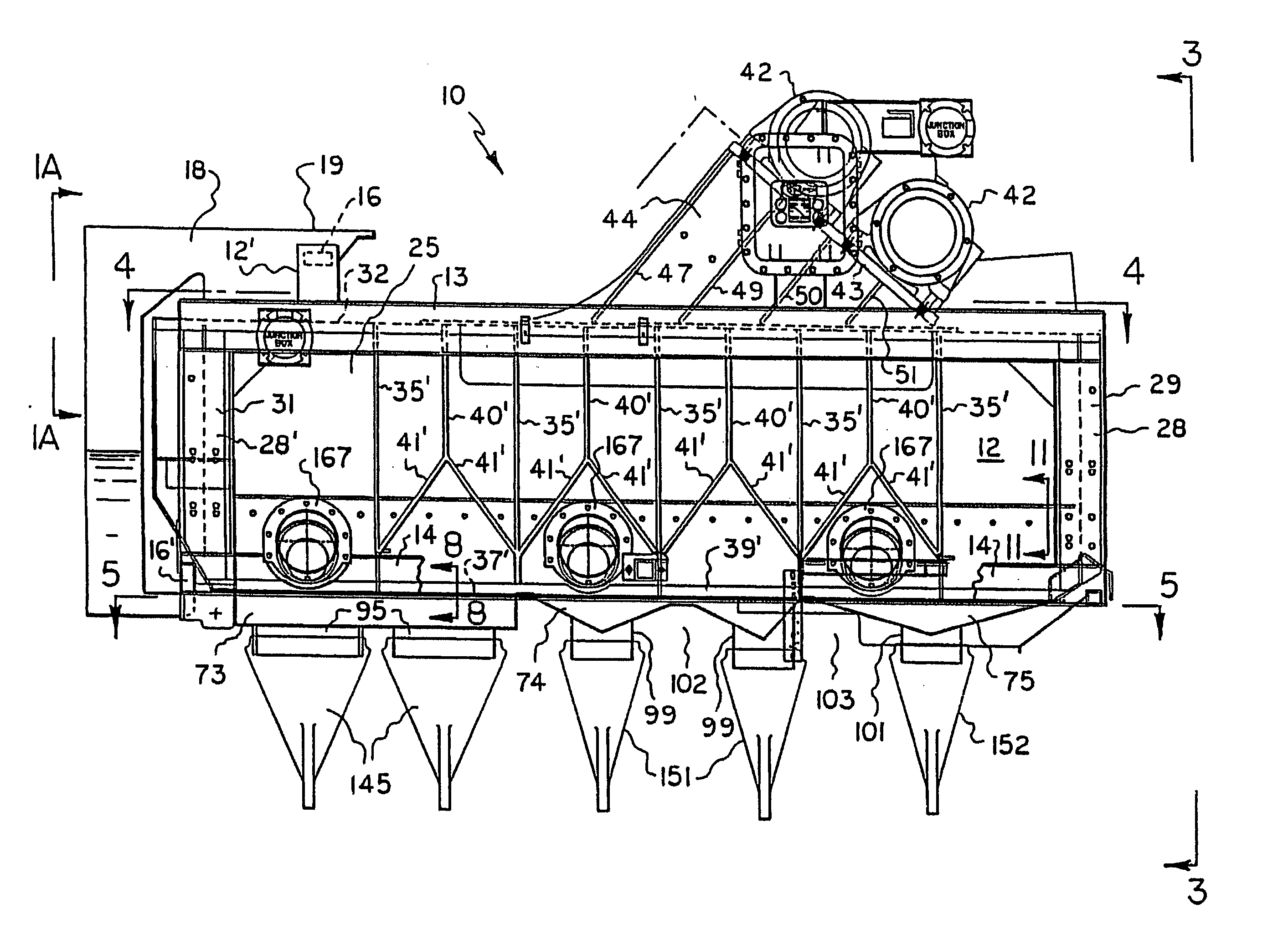
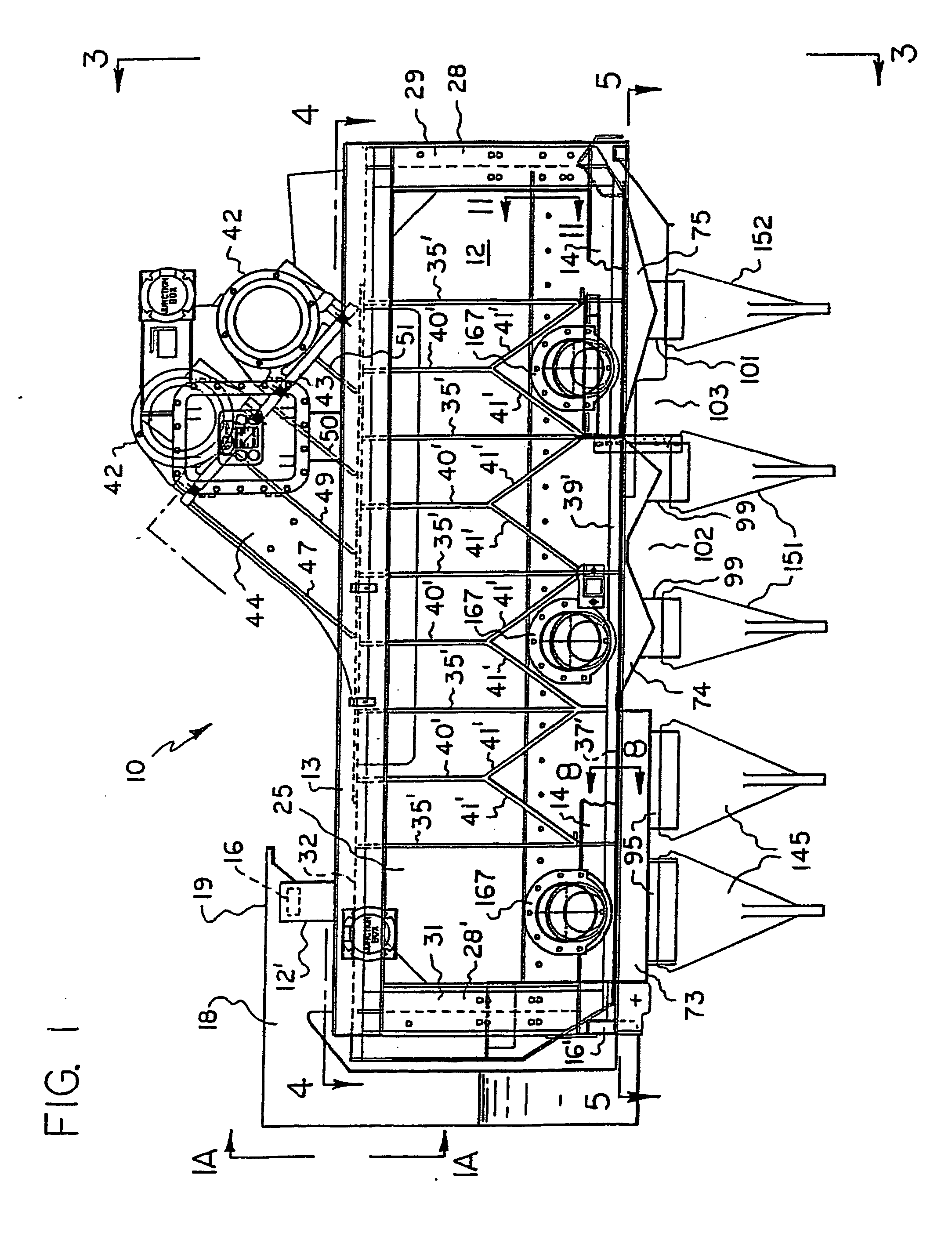
[0007]FIG. 1 is a fragmentary side elevational view of the vibratory screening machine taken substantially in the direction of arrows 1-1 of FIG....


PUM

PropertyMeasurementUnit
transition pointsaaaaaaaaaa
suctionaaaaaaaaaa
structureaaaaaaaaaa

Abstract

A screen assembly comprising a support, a screen comprising peaks and troughs, and a coating on at least a portion of a plurality of the peaks. An apparatus for screening material comprising a frame, a motor mounted to the frame, a screen assembly supported by the frame, a chamber beneath the screen assembly adapted to be placed intermittently at less than atmospheric pressure, a screen formed in an undulating shape comprising a plurality of peaks and troughs, and a coating on at least a portion of a plurality of the peaks.

Description

CROSS-REFERENCE TO RELATED APPLICATIONS [0001] The present application is a continuation-in-part of application Ser. No. 10 / 167,996, filed Jun. 12, 2002.STATEMENT REGARDING FEDERALLY SPONSORED RESEARCH OR DEVELOPMENT [0002] Not Applicable BACKGROUND INFORMATION [0003] Embodiments of the present invention relate to a vibratory screen and a method for manufacturing screens. Such screens may be employed to withdraw liquid and fine particles from a slurry and also to cause coarse particles which are not withdrawn from the slurry to be relatively dry. [0004] By way of background, in the oil drilling process, drilling mud is used for its conventional purposes of lubricating the drill and carrying drilled material to the surface. The combination of drilling mud and drilled material is a slurry of fine drilling mud solids, coarse drilled material particles and liquid. The primary liquid portion of the drilling mud may be oil or water, depending on whether the drilling mud is water-based or ...

Claims


Application Information

Patent Timeline
Patent Type & Authority Applications(United States)
IPC IPC(8): B01D33/03
CPCB01D33/0376B01D2201/204B07B1/42B07B1/46B07B1/4654B07B13/16B01D33/0384B01D33/37B01D33/41B01D33/48
Inventor DERRICK, MITCHELL J.DERRICK, ROBERT G.MOONEY, JAMES A.
Owner DERRICK CORP
Why Eureka
Try Eureka