Method and apparatus for monitoring surfaces

a technology of surface monitoring and apparatus, applied in the direction of optical detection, electrical equipment, instruments, etc., can solve the problems of reducing the signal strength or level generated by the light receiver, increasing increasing the distance, so as to enhance the accuracy of determining the width of the monitoring field, prolong the time interval, and reduce the efficiency of the individual optoelectronic components

Inactive Publication Date: 2005-06-23
SICK AG
View PDF3 Cites 49 Cited by
  • Summary
  • Abstract
  • Description
  • Claims
  • Application Information

AI Technical Summary

Benefits of technology

[0008] An advantage of the present invention is that with no additional optical or optoelectronic components, and by merely using a cyclical or situation-dependent switching between the monitoring mode and the distance determining mode as triggered by a control unit, the width of the monitoring field can be determined so that the optimal switching threshold for the light receivers when operating in the monitoring mode can be established. In this way, a light grid can be used for different monitoring field widths, without compromising the safe recognition of obstacles in the monitoring field, as can be caused, for example, by multiple reflections or the like.
[0009] In one preferred embodiment of the invention, it is not necessary to set the size of the light beam cone from the light emitters (the “sending cone”), or the size of the light receiving cone of the light receivers by means of costly adjustments to exact values during factory assembly of the apparatus. Instead, these values are determined independently during an ongoing teach-in process. For example, this can be carried out for a monitoring field of known width by determining the number of light emitters that are visible from a given light receiver and / or the number of light receivers which can see a given light emitter during the distance determining mode of operation. From this, the angle of the sending cone and / or that of the receiving cone can be calculated.
[0010] In another advantageous preferred embodiment of the invention, the distance information obtained while operating in the distance determining mode is correlated to the signal strength at the light receiver to establish the switching threshold. In this way, one can also factor in the degree of dirtiness or other contamination of the optical boundary surfaces and / or the age-related decrease in the efficiency of the individual optoelectronic components when the switching threshold is set. This has the major advantage of prolonging the time intervals between necessary cleaning of the boundary surfaces.
[0011] In another embodiment of the invention, a mean value is formed from a number of individual values obtained during the distance determining mode, which enhances the accuracy of determining the monitoring field width.
[0012] A further modification of the invention involves using the number of light emitters visible from a light receiver and / or the number of light receivers which can see a light emitter for mechanically aligning of the light emitters with the light receivers and vice versa. For this purpose, for example, the number of light emitters seen by the first light receiver is compared with the number of light emitters seen by the last light receiver. The light emitters and / or light receivers are then shifted or tilted relative to each other until the emitters and / or receivers are symmetrically distributed relative to each other.
[0013] The present invention further proposes to use the number of light emitters that are visible from a light receiver, as determined in the distance determining mode of operation and / or the number of light receivers that can see a light emitter for locating an object positioned in the monitoring field. If the object lies relatively closer to the light emitters, several of the light receivers will not receive any light from the covered light emitter(s). If the object is relatively closer to the light receiver, only one or only a few light receivers will be prevented from receiving light from the light emitters.

Problems solved by technology

A drawback encountered with prior art systems is that the light density within the cone-shaped light beam decreases with an increase in the width of the monitoring field, i.e. an increase in the distance between the light emitter and receiver.
This substantially reduces the signal strength or level generated by the light receiver from the incident light.
But when the monitoring field width is relatively narrow, which results in a very high signal strength that is far above the switching threshold, the light barrier or light grid can experience operational problems.
These problems are usually due to multiple reflections on obstacles or a sensitivity to spurious or background light.
Switching threshold adaptations can be made at the factory, but that would lead to multiple device versions, which is uneconomical to both the manufacturer or the user.
If this switch threshold adaptation is performed by the user, defective settings are possible, which can be dangerous and constitute a safety risk.

Method used


Image

  • Method and apparatus for monitoring surfaces
  • Method and apparatus for monitoring surfaces
  • Method and apparatus for monitoring surfaces

Examples


Embodiment Construction

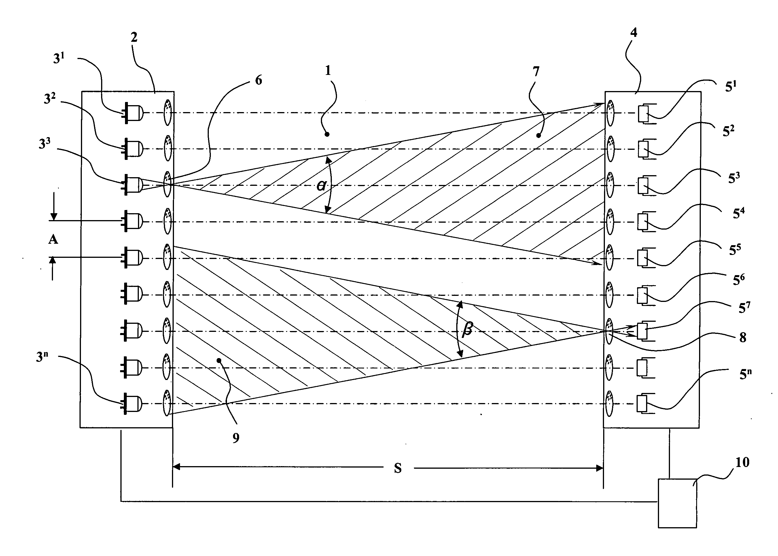
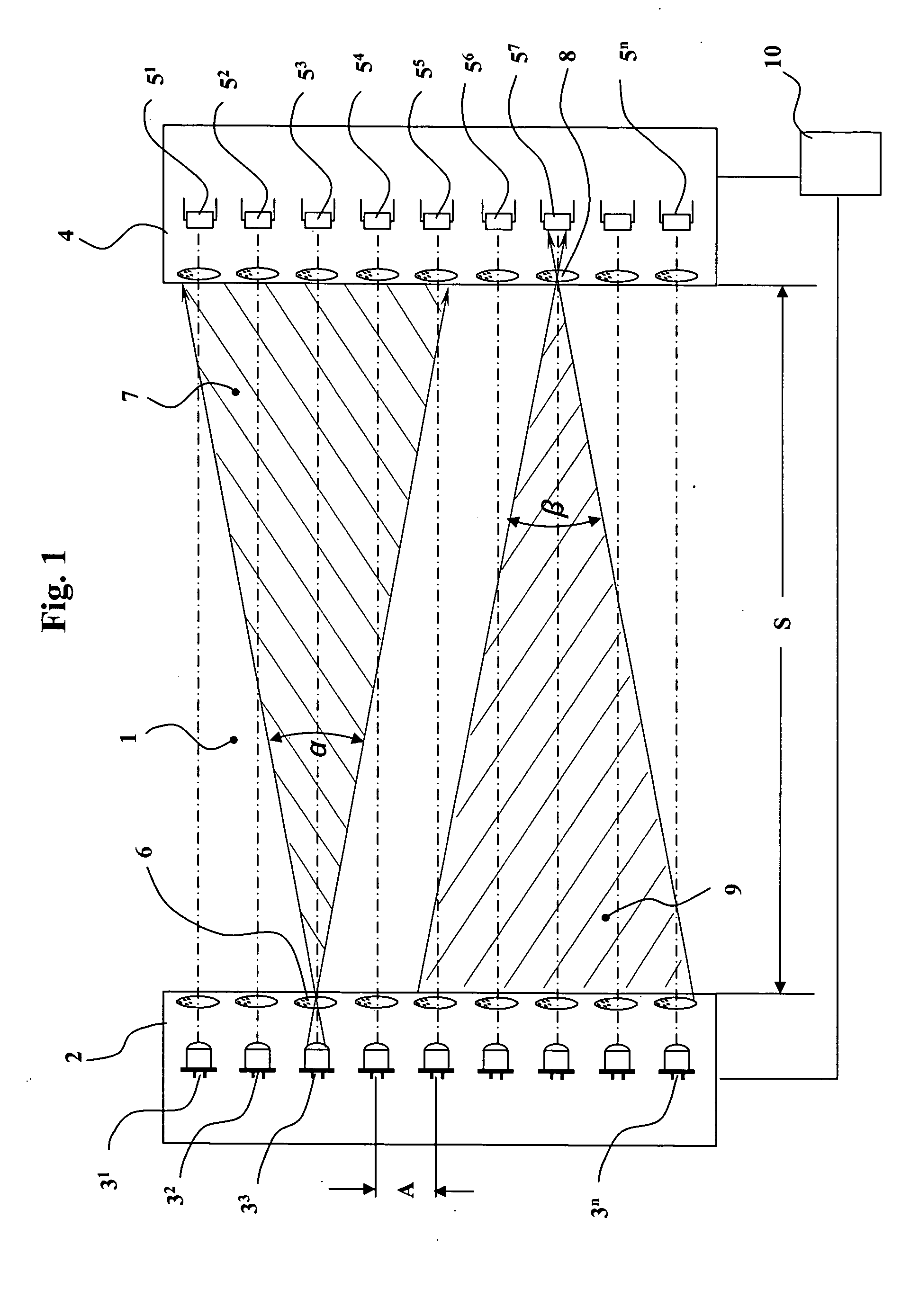
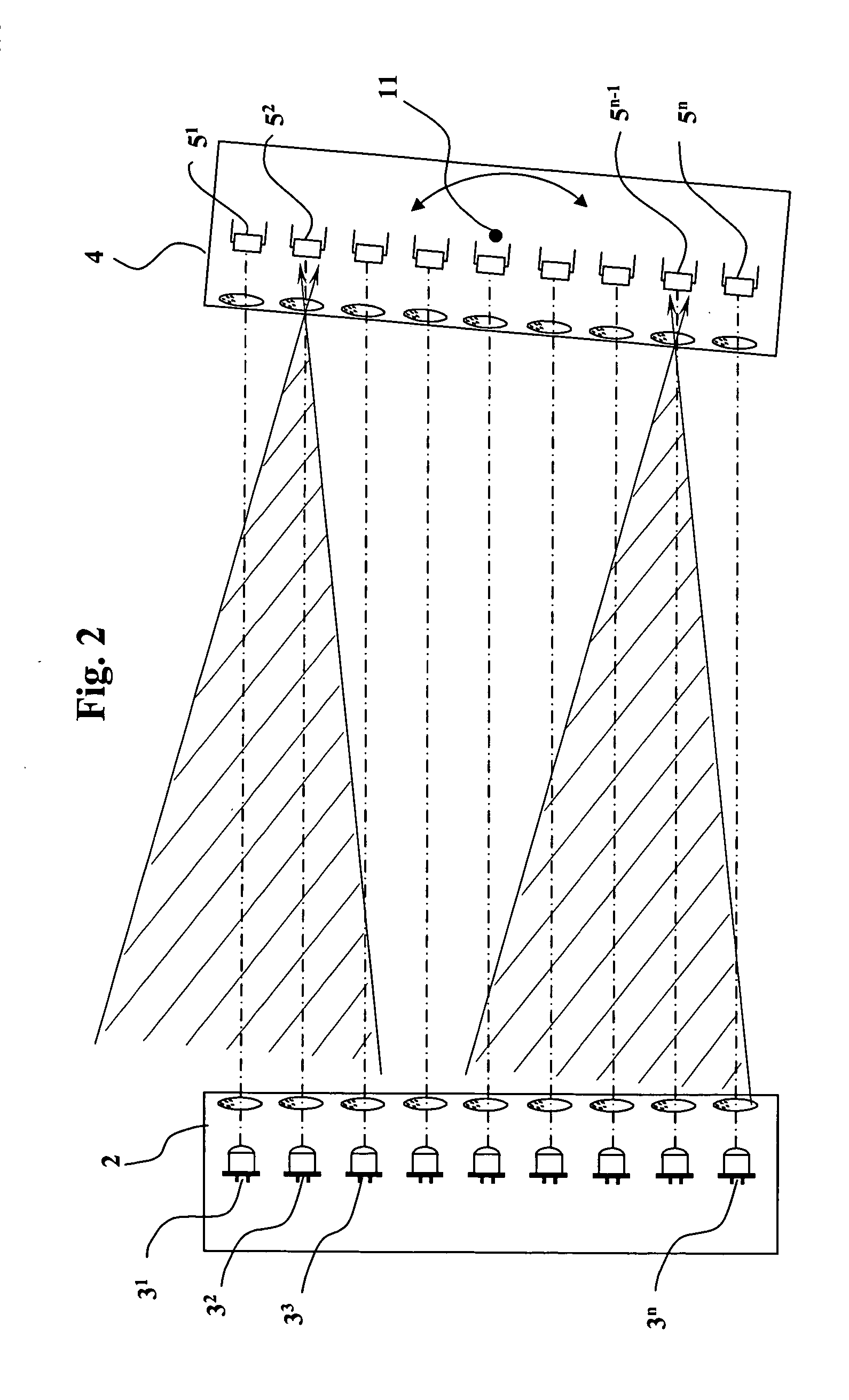
[0018] Referring to FIG. 1, on one side of a monitoring field 1, several light emitters 31, 32, 33 to 3n, arranged alongside each other, are in an emitter housing 2. At the opposite side of the monitoring field 1, several light receivers 51, 52, 53 to 5n are arranged alongside each other in a receiver housing 4. Transmission optics 6 are arranged in front of each light emitter 3 and shape the emitted light directed into the monitoring field into an emitter cone 7 with an emitter cone angle α A receiving lens 8 is positioned in front of each light receiver 5 and concentrates the light arriving within a receiving cone 9, which has an angle β, on the light receiver.

[0019] In the monitoring mode, i.e. when the monitoring field 1 is monitored to detect intruding objects, a control unit 10 activates the light emitter 31 and the light receiver 51 in a pair-wise fashion. During this brief time interval, only the light emitter 31 transmits light into the monitoring field 1, and at the same ...


PUM


Abstract

A method and apparatus for the monitoring of areas with several light emitters arranged alongside each other, which emit light along a light emitter cone, and several light receivers arranged alongside each other, which receive light from a light receiver cone. The emitters and receivers form several interacting pairs which can be activated individually, in temporal succession (sequentially) and / or cyclically by a control unit during a monitoring mode of operation. The distance of the light emitters from the corresponding light receivers is determined during a distance determining mode of operation from the number of light emitters visible to a light receiver and / or from the number of light receivers seeing a light emitter.

Description

BACKGROUND OF THE INVENTION [0001] The invention concerns a method for the contact-free monitoring of areas with several light emitters and corresponding light receivers arranged alongside each other and forming several emitter / receiver pairs that work together to cover the area being monitored with several parallel light beams. The invention also relates to a device for carrying out such a method. [0002] The above-mentioned methods and device are used, for example, to protect and isolate dangerous machine tools with multiple-beam light grids. For this, several light emitters and light receivers are arranged in a common housing on one side of the monitoring area. On the opposite side of the monitoring area is a retroreflector for reflecting the light from the light emitters back to the light receivers. [0003] Such protective systems are also known as one-way systems, in which the light emitters are located on one side of the monitoring area, while the opposite side is bounded by the...

Claims


Application Information

Patent Timeline
Patent Type & Authority Applications(United States)
IPC IPC(8): G01V8/20
CPCG01V8/20
Inventor MEYER, CHRISTOF J.
Owner SICK AG
Why Eureka
Try Eureka