Drive mechanism for vehicle

a technology of driving mechanism and electric motor, which is applied in the field of electric-driven vehicles, can solve the problems of low safety, difficult transportation, and large occupation area of electric-driven vehicles, and achieve the effects of convenient transportation, good stability, and simple structur

Inactive Publication Date: 2005-06-23
XIE SHOUCHUN
View PDF12 Cites 94 Cited by
  • Summary
  • Abstract
  • Description
  • Claims
  • Application Information

AI Technical Summary

Benefits of technology

[0012] Another object of the present invention is to provide an electric-driven vehicle having a simple structure and a good stability.
[0013] A further object of the present invention is to provide an electric-driven vehicle being collapsible ...

Problems solved by technology

However, the structure of the electric-driven vehicle allows only the front wheels steerable, but the rear wheels driven by the power supply not steerable.
In this case, the rear, wheels may be obstructed while the front wheels may just pass by the obstruct, thereby leading to a low safety.
Moreover, the electric-driven vehicle does not only occupy a large occupation area, but also unwieldy, un-collapsible and difficult for transportation.
Furthermore, it is insecure for a rider during the running of the vehicle as it might be in a state with three wheels on the ground but one wheel hanging in the air when it is on the uneven ground due to the rigidity of the chassis frame.
This electric-driven vehicle has a structure of two driving rear wheels and one steering front wheel may easily turnover in the driving, which leads to instability.
When a rider drives the electric-driven vehicle, he/s...

Method used


Image

  • Drive mechanism for vehicle
  • Drive mechanism for vehicle
  • Drive mechanism for vehicle

Examples


Embodiment Construction

[0057] The present invention will now be described in detail in conjunction with the accompanying drawings.

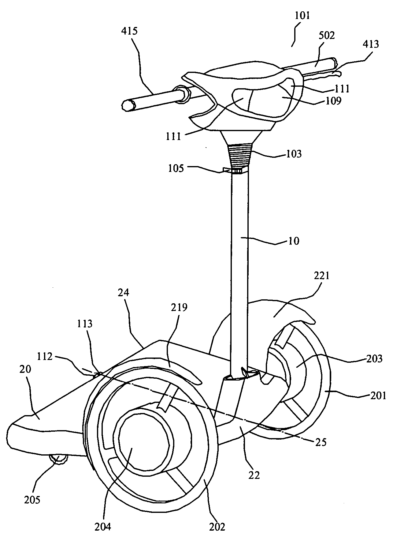
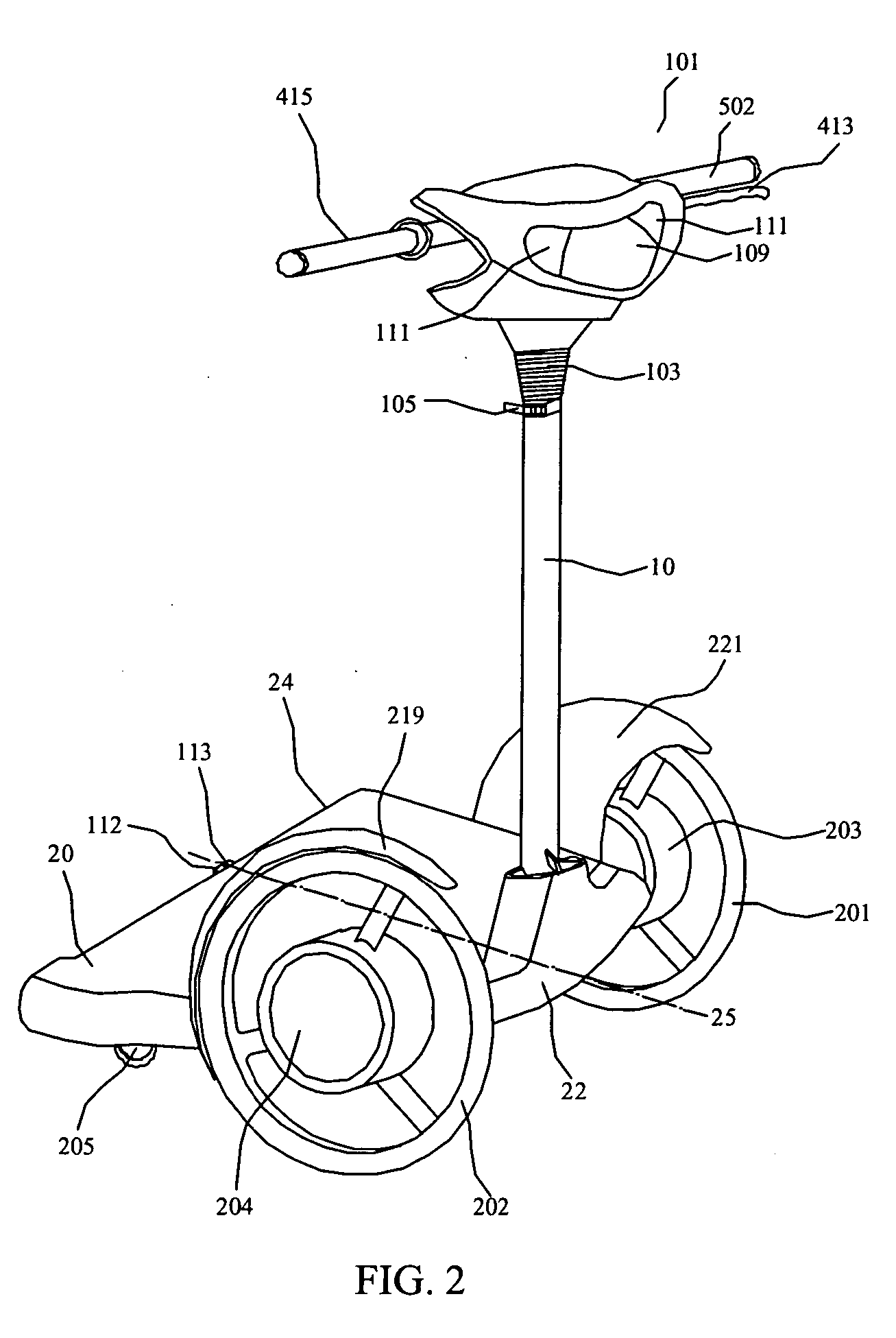
[0058]FIG. 2 is a perspective structural view of an electric-driven vehicle according to the present invention. As shown in FIG. 2, the electric-driven vehicle comprises a upright tube 10 and a supporting platform 20, wherein the supporting platform 20 has a first end 22 and a second end 24 (or front and rear ends, respectively), and a longitudinal axis 25 perpendicular to the first end 22 and the second end 24. The upright tube 10 is pivotally connected with the supporting platform 20 at the first end 22 of supporting platform 20. A steering handle frame 101 is provided at an up end of the upright tube 10. Wires and braking cables (not shown) are received in the upright tube 10. A left driving wheel 201 and a right driving wheel 202 are respectively provided at opposite sides of the first end 22 of the supporting platform 20. A left electric hub 203 and a right electric hub 2...


PUM


Abstract

The present invention provides an electric-driven vehicle, which comprises a supporting platform and an upright tube, wherein the supporting platform has first and second ends and a longitudinal axis perpendicular to the first and second ends, the upright tube is fitted at the first end of the supporting platform and operatively connected with the supporting platform, a handle frame is provided on a top end of the upright tube. The electric-driven vehicle further includes two driving wheels operatively mounted at opposite sides of the first end of the supporting platform, at least one steering wheel operatively mounted on a bottom of the second end of the supporting platform, a driving means for the driving wheels, and a power supply means mounted on the bottom of the supporting platform and electrically connected with the driving means. The present invention also provides a support platform structure for an electric-driven vehicle, which comprises a first portion and a second portion, wherein the first portion having sleeves for operatively mounting the driving wheels, and a first side; the second portion having a steering knuckle for operatively mounting the steering wheels, and a second side corresponding to the first side; the first side and the second side are connected via a connecting member, and at least one of the first side and the second side can rotate about the bond-linkage element.

Description

CLAIM OF PRIORITY [0001] This application claims priority to Chinese Patent Application No. 2003201279777 filed on Dec. 17, 2003 and Chinese Patent Application No. 2004200006141 filed on Jan. 12, 2004 under 35 U.S.C. §119(e) and are hereby incorporated by reference in their entirety herein. BACKGROUND OF THE INVENTION [0002] 1. Field of the Invention [0003] The present invention relates to vehicles, and particularly, to an electric-driven vehicle. [0004] 2. Description of the Related Art [0005] Nowadays, vehicles have become transportation means indispensable in people's daily life, such as automobiles and motorcycles. However, in order to decrease the air pollution caused by vehicles, various electric-driven vehicles have been developing. [0006] Chinese Patent No. ZL 02216290.9 disclosed a four-wheel electric-driven vehicle. It has a chassis frame, a handle frame, a seat, a rechargeable battery, two front wheels, and two rear wheels. The handle frame is operatively provided at a fr...

Claims


Application Information

Patent Timeline
IPC IPC(8): B62D51/00B62D51/02B62K3/00
CPCB62D51/001B62K3/002B62D51/02B62D51/004
Inventor XIE, SHOUCHUN
Owner XIE SHOUCHUN
Why Eureka
Try Eureka