Fitting for fluid conveyance

a technology of fluid conveyance and fittings, which is applied in the direction of pipe joints, pipe expansion compensation, and pipe units with cleaning apertures, etc., can solve the problems of difficult to achieve reliable sealing of the tube, high cost and time consumption of subsequent recoating, and protect the coating, so as to eliminate the number of steps required for installation, eliminate the environmental impact of resulting waste streams, and eliminate the effect of waste of tubing

Inactive Publication Date: 2005-06-23
EATON CORP
View PDF9 Cites 87 Cited by
  • Summary
  • Abstract
  • Description
  • Claims
  • Application Information

AI Technical Summary

Benefits of technology

[0006] Fluid connectors are provided that eliminate the number of steps required for installation, eliminate required brazing and coating processes and the environmental impact of resulting waste streams, eliminate wasted tubing, and/or reduce the cost of installation. Since industry accepted pre-coated tube is used, the need for multiple sites for plating is eliminated. The connector can be slid onto the tube, th

Problems solved by technology

While these prior art connectors may be adequate for their intended purpose, disadvantages for particular applications exist.
One disadvantage of a brazed connector is that any protective coating, such as a corrosion resistance coating, or surface on the tubing and connector must be reapplied after the brazing process since the heat of

Method used


Image

  • Fitting for fluid conveyance
  • Fitting for fluid conveyance
  • Fitting for fluid conveyance

Examples


Embodiment Construction

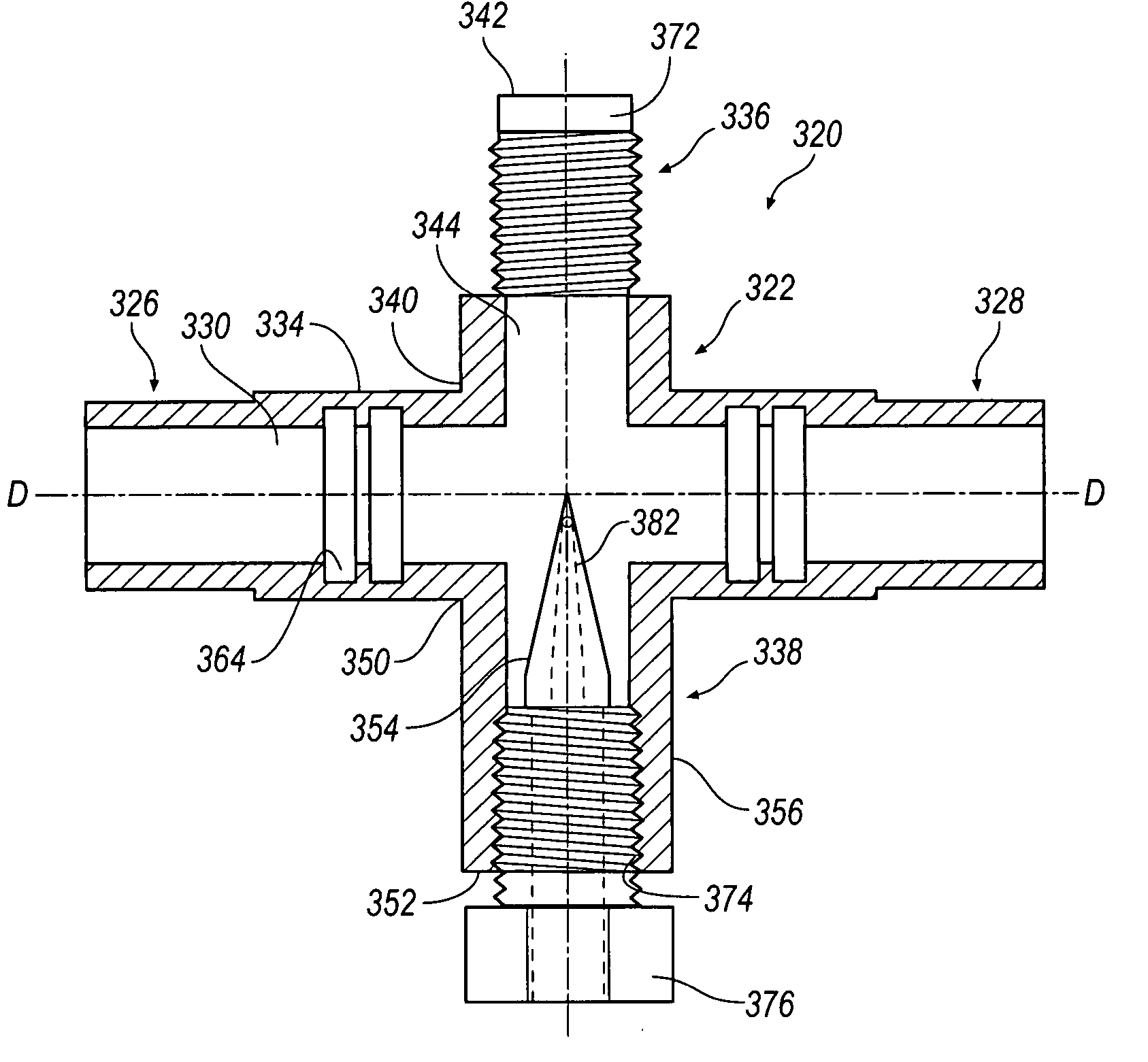
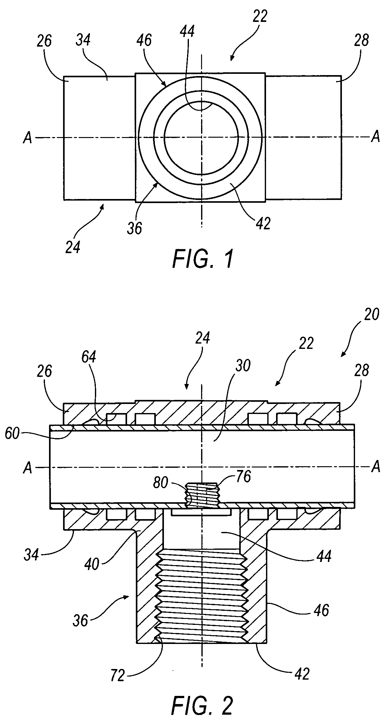
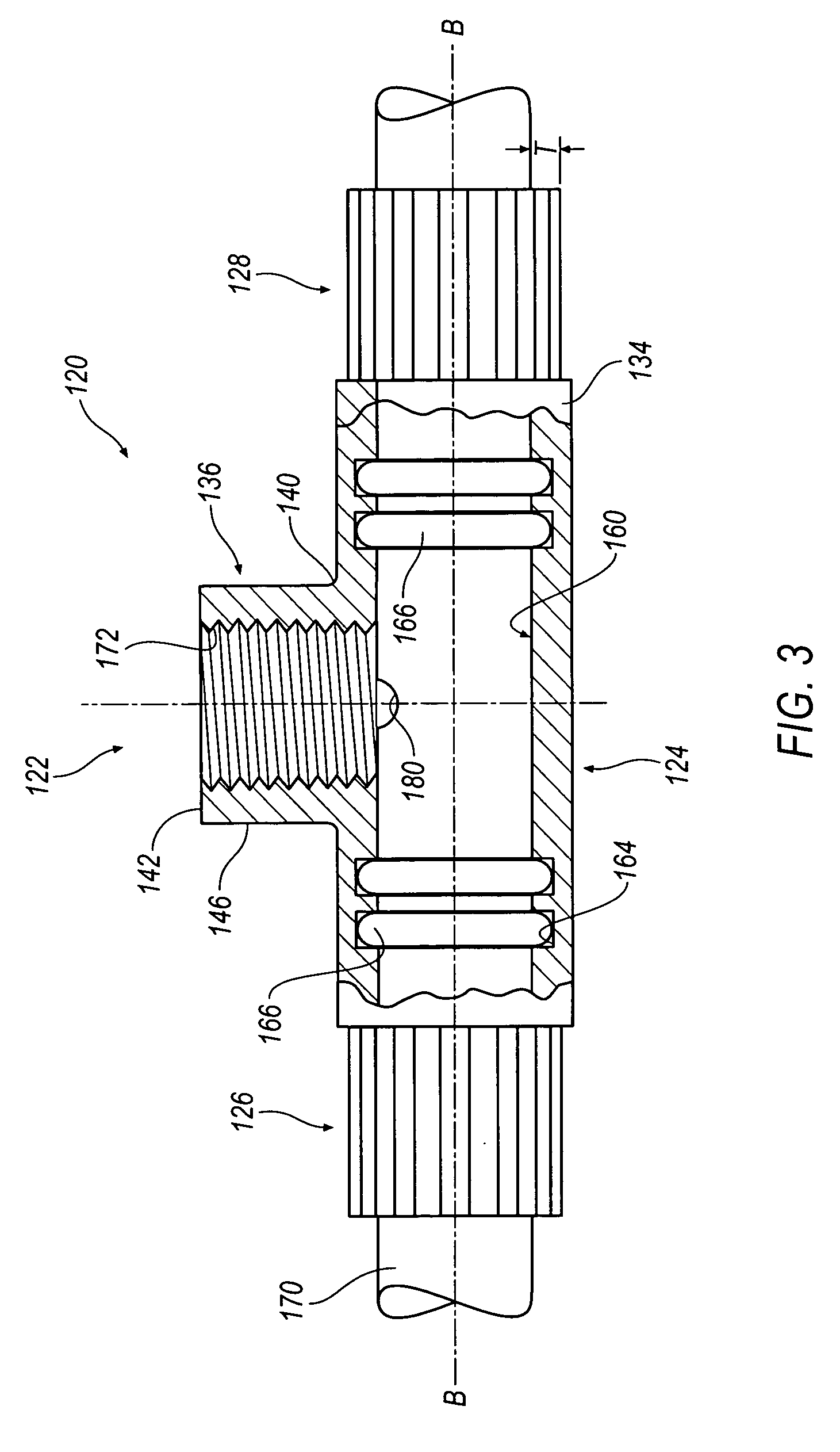
[0016] Referring to FIGS. 1 and 2, a fitting, coupling, or connector 20 is illustrated. Connector 20 includes a main body 22 having a main portion 24 extending from a first end 26 to a second end 28, and defining a main passageway 30 having an axis A-A and an outer surface 34. Main body 22 further includes a branch portion 36 extending from main portion 24 at a branch end 40 to a third end 42 and defining a branch passageway 44 and an outer surface 46.

[0017] As best seen in FIG. 2, main portion 24 includes a generally cylindrical surface 60 defining the main passageway 30 with annular grooves 64 formed therein. Annular grooves 64, as discussed below, accommodate seals (not shown). Branch passageway 44 is in fluid communication with main passageway 30. An integral main conduit 70 is interposed through main passageway 30, extending beyond first and second ends 26, 28. A piercing member, or hollow screw, 76 is shown extending through an aperture 80 formed in main conduit 70. Branch po...


PUM


Abstract

A fitting for a fluid connector comprising a body that accepts a main conduit and connects to a branch conduit where the main conduit is inserted through an opening in the body. An aperture is formed in the main conduit such that the main conduit and branch conduit are in fluid communication.

Description

CROSS REFERENCE TO RELATED APPLICATIONS [0001] This application claims priority to Provisional Application 60 / 530,687, filed on Dec. 17, 2003, the contents of which are hereby incorporated by reference herein in their entirety.TECHNICAL FIELD [0002] The present invention relates to fluid fittings or connectors for tubing and in particular to a connector that provides a branch connection for a tube without separating the tube. BACKGROUND OF THE INVENTION [0003] There are many industrial applications where a relatively high pressure hydraulic system requires that branch connections be made between a tube and a component such as another fluid handling system, pump, motor, valve, switch, sensing device or the like. The fluid transfer tube may be made out of steel, aluminum, or a copper material where bonding methods in addition to brazing are used to attach the additional outlet, commonly known as a “T-fitting”. Prior art hydraulic systems have historically involved separating the tubin...

Claims


Application Information

Patent Timeline
IPC IPC(8): F16L41/00F16L41/02F16L41/03F16L41/06
CPCF16L41/021F16L41/065F16L41/03F16L41/023F16L13/142
Inventor WALSH, BRIAN J.
Owner EATON CORP
Why Eureka
Try Eureka