Liquid crystal display device and method of fabricating the same

Active Publication Date: 2005-06-23
LG DISPLAY CO LTD
View PDF3 Cites 56 Cited by
  • Summary
  • Abstract
  • Description
  • Claims
  • Application Information

AI Technical Summary

Benefits of technology

[0017] Accordingly, the present invention is directed to an LCD device and a method of fabricating an LCD dev

Problems solved by technology

Because liquid crystal molecules adjacent to the gate lines, data lines and the thin film transistors may be abnormally driven so as to cause light leakage, the black m

Method used


Image

  • Liquid crystal display device and method of fabricating the same
  • Liquid crystal display device and method of fabricating the same
  • Liquid crystal display device and method of fabricating the same

Examples


Embodiment Construction

[0031] Reference will now be made in detail to the preferred embodiments of the present invention, examples of which are illustrated in the accompanying drawings.

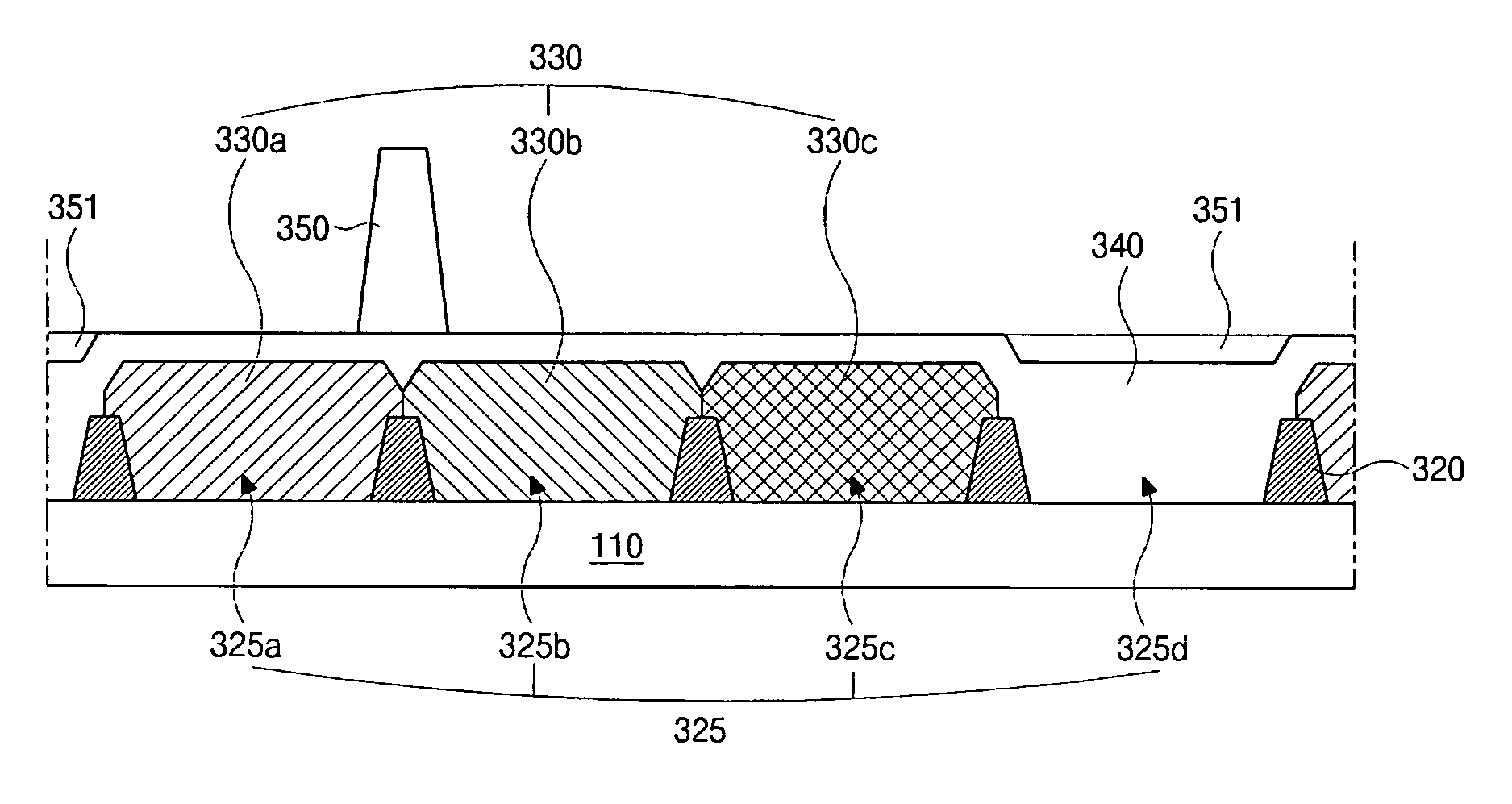
[0032]FIG. 4 is a cross-sectional view of a color filter substrate for an LCD device according to an embodiment of the present invention. As shown in FIG. 4, a black matrix 320 having openings 325 is formed on a substrate 310. A color filter layer 330 is formed on the substrate 310 and corresponds to the openings 325 of the black matrix 320. An overcoat layer 340 is formed on the color filter layer 330. A column spacer 350 and a planarization pattern 351 are formed on the overcoat layer 340.

[0033] The black matrix 320 is formed of a light-blocking material and corresponds to gate and data lines and thin film transistors, which are not shown in FIG. 4 and are formed on a substrate facing the color filter substrate. Because liquid crystal molecules adjacent to the gate lines, data lines and the thin film transistors may be ...


PUM


Abstract

A liquid crystal display device having a pixel, including red, green, blue and white sub-pixels, the device includes: red, green and blue color filters on a substrate, the red, green and blue color filters corresponding to the red, green and blue sub-pixels, respectively; an overcoat layer on a surface of the substrate in the white sub-pixel and also on the red, green and blue color filters; a planarization pattern on the overcoat layer corresponding to the white sub-pixel; and a column spacer on the overcoat layer.

Description

[0001] This application claims the benefit of Korean Patent Application No. 2003-0095730 filed in Korea on Dec. 23, 2003, which is hereby incorporated by reference.BACKGROUND OF THE INVENTION [0002] 1. Field Of The Invention [0003] The present invention relates to a liquid crystal display (LCD) device and a method of fabricating the same, and more particularly, to a color filter substrate for an LCD device and a method of fabricating the same. [0004] 2. Discussion Of The Related Art [0005] A liquid crystal display (LCD) device is driven based on the optical anisotropy and birefringence characteristics of a liquid crystal material to display images. In general, the LCD device includes two substrates that are spaced apart and face each other, and a liquid crystal material layer interposed between the two substrates. Each of the substrates includes electrodes that face each other, wherein a voltage applied to each electrode induces an electric field perpendicular to the substrates betw...

Claims


Application Information

Patent Timeline
IPC IPC(8): G02F1/1339G02F1/1333G02F1/1335
CPCG02F1/133514G02F2001/133519G02F1/13394G02F1/133519G02F1/1339
Inventor KANG, WON-SEOK
Owner LG DISPLAY CO LTD
Why Eureka
Try Eureka