HDD tray structure

Active Publication Date: 2005-06-23
QUANTA COMPUTER INC
View PDF7 Cites 12 Cited by
  • Summary
  • Abstract
  • Description
  • Claims
  • Application Information

AI Technical Summary

Benefits of technology

[0011] Hence, with the application of the present invention, the design for controlling the indicators of the HDD tray can be greatly simplified, and the shock-absorbi

Problems solved by technology

However, since the light pipes are restricted by space and turning angles, it is not easy to guide the light to the front with the light pipes.
With the addition of the other wire connecting devices, the design becomes more difficult to install the light

Method used


Image

  • HDD tray structure
  • HDD tray structure
  • HDD tray structure

Examples


Embodiment Construction

[0015] A flexible printed circuit board (FPC) is one of the popular devices recently, and the function thereof is to hold copper plate circuits. Since the FPC has the features of light weight, soft and thin material, small volume, good ductility, high wiring density, good wiring capability in 3-D space and excellent flexibility in shape in accordance with the space limitation. Hence, the FPC is widely applied in the products, such as notebook computers, mobile phones, personal digital assistants (PDAs) and digital information appliances (IAs), etc. With respect to the functions, the FPC includes four types: a lead line, a printed circuit, a connector and a multi-function integrating system.

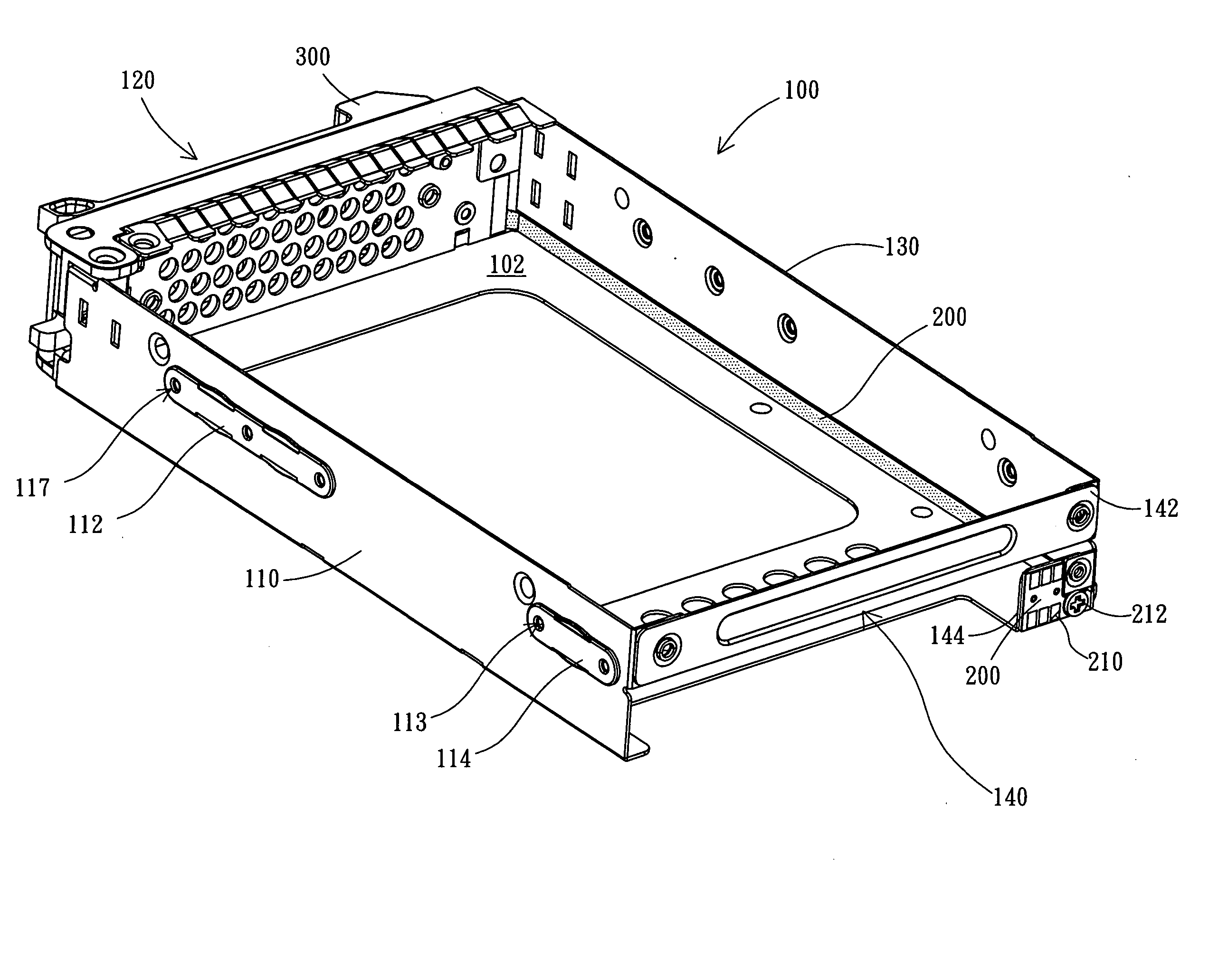
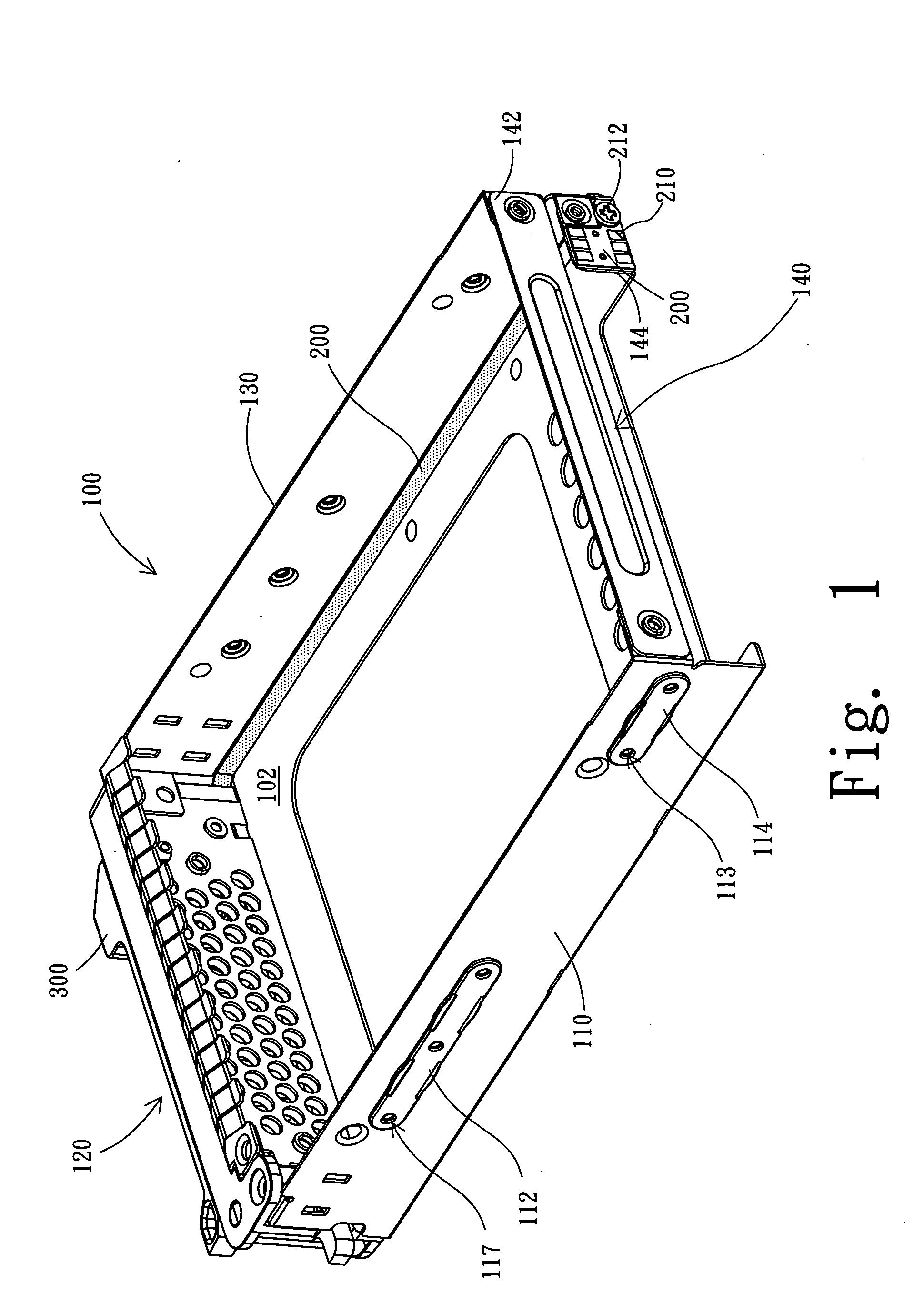
[0016] The present invention is featured in using a FPC to control the indicators of a HDD tray.

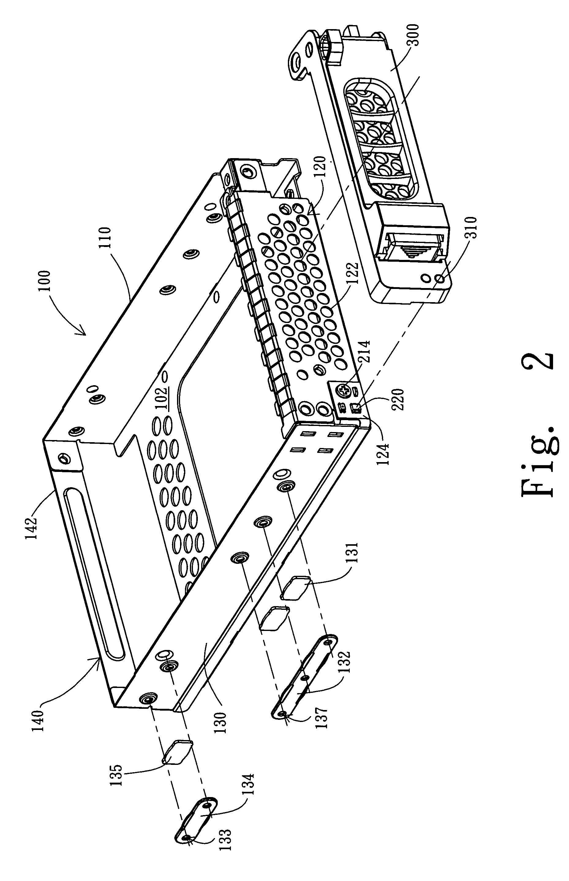
[0017] Referring to FIG. 1 and FIG. 2, FIG. 1 is a 3-D schematic diagram depicting a HDD tray of the present invention, and FIG. 2 is an explosive schematic diagram showing an outer cover, metal elast...


PUM


Abstract

A HDD tray structure is disclosed. The HDD tray structure includes a tray housing, a flexible printed circuit board (FPC) installed on the tray housing, and at least one indicators, wherein one end of the FPC has a metal pad electrically connected to a connector of a printed circuit board, and the other end of the FPC is in electrical contact with the indicator, so as to control the on/off state of the indicator.

Description

FIELD OF THE INVENTION [0001] The present invention relates to a HDD (Hard Disk Drive) tray structure, and more particularly, to the HDD tray structure with a FPC (Flexible Printed Circuit Board) for controlling an indicator of the HDD tray. BACKGROUND OF THE INVENTION [0002] A hard disk drive is quite an important information storage apparatus for a computer product, and more and more computers are equipped with more than two hard disk drives, so that the indicators (indicating lights) have become essential devices for showing the statuses of the hard disk drives. For installing or removing the hard disk drives conveniently and safely, each of the hard disk drives is placed in a HDD tray, so that the HDD tray is a proper place to install the indicators for the hard disk drives. [0003] Plastic light pipes are used to guide light in the conventional technology for lightening the HDD indicators. However, since the light pipes are restricted by space and turning angles, it is not easy ...

Claims


Application Information

Patent Timeline
IPC IPC(8): G06F1/18G11B33/02G11B33/12
CPCG06F1/184G06F1/187G11B33/124G11B33/122G11B33/022
Inventor KAO, CHIH-WEILEE, CHENG-CHENGLEE, CHIH-WEI
Owner QUANTA COMPUTER INC
Why Eureka
Try Eureka