Method for identifying track capacity

a track capacity and optical disk technology, applied in the field of optical disk track capacity identification, can solve the problems of inability to fix the track length, consume too much time for track-seeking (or tracking), and negative system performance, so as to reduce the required time for performing track-seeking and improve the calculation efficiency of track capacity

Inactive Publication Date: 2005-06-23
MEDIATEK INC
View PDF4 Cites 1 Cited by
  • Summary
  • Abstract
  • Description
  • Claims
  • Application Information

AI Technical Summary

Benefits of technology

[0010] One advantage of the present invention is that the write mode of the target track can be correctly determined by checking if any track having link blocks exists in the session that the target track belongs to.
[0011] Another advantage of the present invention is that the actual track capacity of the target track can be obtained by calculating the track capacity of the target track according to its write mode.
[0012] Yet another advantage of the present invention is it reduces required time for performing track-seeking when the optical disk drive calculates the track capacity and thereby improves calculation efficiency of track capacity.
[0013] These and other objectives of the present invention will no doubt become obvious to those of ordinary skill in the art after reading the following detailed description of the preferred embodiment that is illustrated in the various figures and drawings.

Problems solved by technology

The length of track, however, is not fixed.
Furthermore, another problem of the related art is that it consumes too much time to perform track-seeking (or tracking) and to access the track descriptor block (TDB) of the target track.
The above-mentioned action has a negative effect for system performance.

Method used


Image

  • Method for identifying track capacity
  • Method for identifying track capacity
  • Method for identifying track capacity

Examples


Embodiment Construction

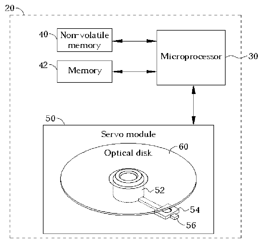
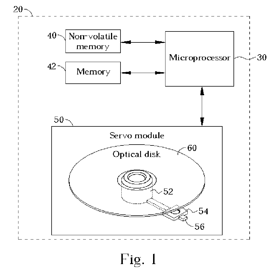
[0017]FIG. 1 illustrates a schematic diagram of an optical disk drive 20 in accordance with the present invention. The optical disk drive 20 comprises a microprocessor 30, a non-volatile memory 40, a memory 42, and a servo module 50. The servo module 50 has a spindle 52, a pick-up head 54, and other required electrical components. The spindle 52 is used for rotating an optical disk 60; the pick-up head 54 slides along a guide bar 56 to access data on different tracks of the optical disk 60. When the optical disk receives a instruction to query about the track capacity of a track on the optical disk 60 from a host (not shown), the optical disk drive 20 utilizes the microprocessor 30 to execute firmware code stored in the non-volatile memory 40 in order to control the servo module 50 to access the optical disk 60. In a preferred embodiment, the non-volatile memory 40 can be a flash memory and the optical disk drive 20 can be a read-only optical disk drive or a recordable optical disk ...


PUM

PropertyMeasurementUnit
sizeaaaaaaaaaa
areaaaaaaaaaaa
lengthaaaaaaaaaa

Abstract

A method for identifying the track capacity of a track on an optical disk, the method includes utilizing an optical disk drive to determine if any link block exists in any track of a session having a target track; determining the write mode of the target track; and calculating the track capacity of the target track according to its write mode. If the write mode of the target track is disk-at-once, session-at-once, or RAW mode, the pre-gap is excluded from the track capacity of the target track. If the write mode is track-at-once or variable packet write mode, the pre-gap and link blocks in track end is excluded from the track capacity of the target track. If the write mode is in fixed packet write mode, the pre-gap and link blocks among all packets within the target track is excluded from the track capacity of the target track.

Description

BACKGROUND [0001] The present invention relates to a method for identifying the track capacity of an optical disk, and more particularly, to a method for identifying the track capacity of an optical disk in an optical disk drive. [0002] As information technology advances, optical disks are widely applied in data storage. In general, a track is the basic unit of measurement for recorded data in an optical disk. The length of track, however, is not fixed. For example, in the case of music CDs, each song is a single track, and in the case of data CDs, it is possible that a plurality of files is stored in a single track. [0003] There are many kinds of write modes for optical disks, such as disc-at-once (DAO), session-at-once (SAO), RAW, track-at-once (TAO), fixed packet write (FPKT), variable packet write (VPKT), and so on. In the case of DAO or SAO, data is written onto an optical disk all at once in the form of a session, wherein each track of the session has no link blocks. In the ca...

Claims


Application Information

Patent Timeline
Patent Type & Authority Applications(United States)
IPC IPC(8): G11B7/00G11B7/085G11B19/12G11B20/12G11B27/32G11B27/36
CPCG11B19/12G11B20/1217G11B27/329G11B27/36G11B2020/1235G11B2020/1238G11B2220/2545G11B2020/1292G11B2220/20G11B2220/216G11B2220/218G11B2220/2537G11B2020/1277
Inventor WU, YUAN-TINGWU, TSE-HONG
Owner MEDIATEK INC
Why Eureka
Try Eureka