Loop fabric

Active Publication Date: 2005-06-23
3M INNOVATIVE PROPERTIES CO
2 Cites 24 Cited by

AI-Extracted Technical Summary

Problems solved by technology

However, the backings are generally specialize...

Method used

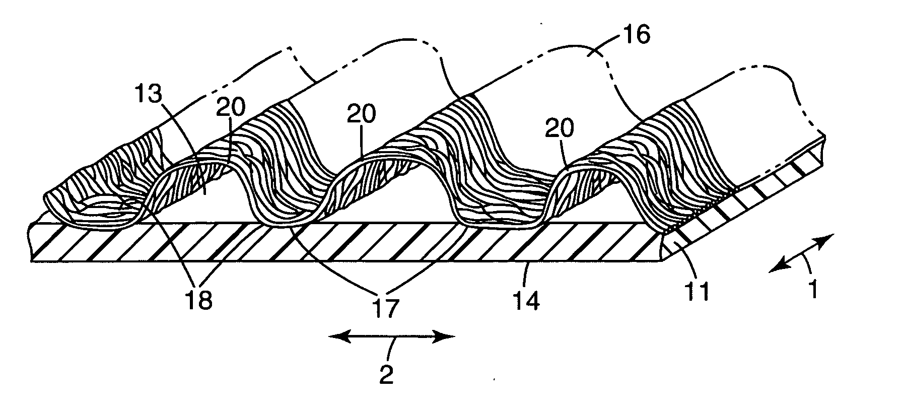
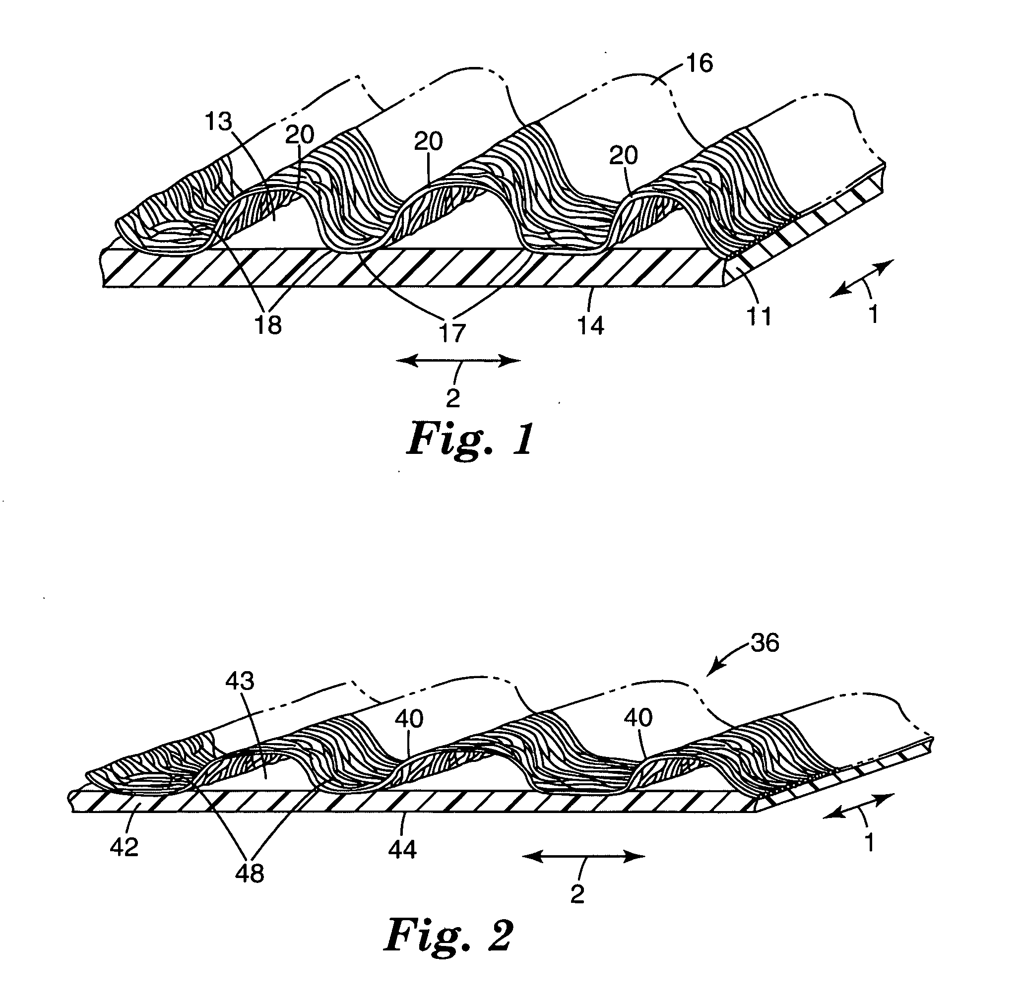
[0012] The invention composite loop fabric is preferably formed by extruding inelastic film onto anchor portions of a first sheet of flexible nonwoven material formed to have arcuate portions extending from the anchor portions followed by orientation to provide a strengthened loop composite. The molten film encapsulates the fibers of the anchor portions creating bond sites. The molten film can form bond sites along all or a part of the film length where there are anchor portions, (e.g., a flat portion of the nonwoven material). The solidified inelastic film has a generally uniform morphology along its length including at the bond sites. The film can be pressed against the anchor portions at the bond sites increasing the bond strength between the nonwoven sheet and the film.
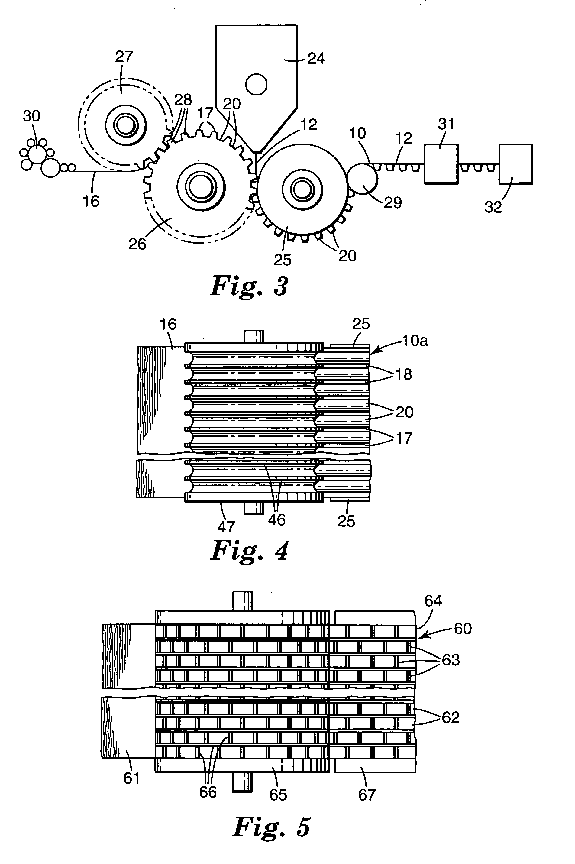
[0020] Corrugating members 26 and 27, as shown in FIG. 3, adapted to have a nonwoven fibrous web 16 fed into them, can have ridges 28 oriented generally in the range of 0 to 45 degrees with respect to its axes, but preferably have its ridges 28 oriented at 0 degrees with respect to (or parallel to) its axes which simplifies making of the corrugating members 26 and 27.
[0027] Generally, the nonbonded portions of the nonwoven fibrous web are from 99.5 to 50 percent providing bonded areas over from 50 to 0.5 percent of the surface area of the nonwoven fibrous web, preferably, the overall bonded area of the nonwoven is from 20 to 2 percent. The bonded areas include thos...

Benefits of technology

[0003] All these methods of forming loops stress the importance of the loop fibers to project outwardly from a backing or base layer. This increases the availability of the fibers to engage suitable hook elements. However, the backings are generally specialized and costly, dimensionally unstable, or thick. It is desired to provide a loop material having projecting loop fibers on a backing that is thin, high strength (dimensionally stable) low cost and easy to manufacture.
[0004] The present invention provides improved inelastic, dimensionally stable, high strength loop composite comprising an oriented inelastic film extending in at least a first direction and one or more sheets of flexible nonwoven material intermittently bonded along at least one surface portion of the oriented inelastic film. Preferably, the loop has regularly spaced bond portions between the nonwoven material and the oriented film. These intermittent bond anchor portions are separated by unbonded portions where the film and nonwoven material face each other, but are not bonded. These loop composites provide unique advantages as a low cost, flexible or soft, dimensionally stable, high performing loop which is relatively simple to manufacture.
[0005] A...

Abstract

This invention relates to a low cost loop material for a hook and loop fastener having at least one sheet of flexible nonwoven material intermittently bonded to inelastic oriented film. The invention further relates to methods for producing these loops.

Application Domain

Technology Topic

Image

  • Loop fabric
  • Loop fabric
  • Loop fabric

Examples

  • Experimental program(12)

Example

Example 1
[0035] The nonwoven loop composite C1 was biaxially oriented using a KARO IV pantograph stretcher (Bruckner Gmbh, Siegfred, Germany). A 115 mm by 115 mm sample was cut from the web of the composite and mounted in the stretcher. The sample was heated for 60 seconds at 140° C. and then stretched at a rate of 100%/sec to a final dimension of approximately 150 mm by 150 mm resulting in a biaxial orientation of 1.5 to 1 in both the machine and cross directions of the sample. The sample was removed from the stretcher and tested for tensile strength and peel and shear properties.
Comparative Example C2
[0036] A nonwoven loop composite was prepared as in C1 except the basis weight of the input fiber web was 28 grams per square meter, and the basis weight of the extrudate was 30 grams per square meter.

Example

Example 2
[0037] The nonwoven loop composite C2 was oriented in the cross direction using a KARO IV pantograph stretcher. A 115 mm by 115 mm sample was cut from the web of the composite and mounted in the stretcher. The sample was heated for 60 seconds at 140° C. and then stretched in the cross direction at a rate of 100%/sec to a final dimension of approximately 100 mm by 250 mm resulting in a cross direction orientation of 2.5 to 1. The sample was removed from the stretcher and tested for tensile strength and peel and shear properties.

Example

Example 3
[0038] The nonwoven loop composite C2 was oriented in the machine direction using a KARO IV pantograph stretcher. A 115 mm by 115 mm sample was cut from the web of the composite and mounted in the stretcher. The sample was heated for 60 seconds at 140° C. and then stretched in the machine direction at a rate of 100%/sec to a final dimension of approximately 250 mm by 100 mm resulting in a machine direction orientation of 2.5 to 1. The sample was removed from the stretcher and tested for tensile strength and peel and shear properties.

PUM

PropertyMeasurementUnit
Fraction0.1fraction
Fraction0.2fraction
Fraction0.2 ~ 0.99fraction
tensileMPa
Particle sizePa
strength10

Description & Claims & Application Information

We can also present the details of the Description, Claims and Application information to help users get a comprehensive understanding of the technical details of the patent, such as background art, summary of invention, brief description of drawings, description of embodiments, and other original content. On the other hand, users can also determine the specific scope of protection of the technology through the list of claims; as well as understand the changes in the life cycle of the technology with the presentation of the patent timeline. Login to view more.

Similar technology patents

Classification and recommendation of technical efficacy words

  • Easily manufacture
  • Increase availability

Dispensing system

ActiveUS20070278164A1Easily manufacturePrevent theftRacksShow shelvesFixed Slide
Owner:WESTROCK SHARED SERVICES LLC

Method and system for consistent cluster operational data in a server cluster using a quorum of replicas

InactiveUS6938084B2Maintain consistencyIncrease availabilityResource allocationDigital data processing detailsMutual exclusion algorithmsOnline and offline
Owner:MICROSOFT TECH LICENSING LLC

Methods and apparatus for testing a circuit board using a surface mountable adaptor

InactiveUS6906544B1Minimize necessityIncrease availabilityPrinted circuit testingContactless circuit testingElectricityEngineering
Owner:CISCO TECH INC
Why Eureka
Try Eureka