
Auto-diagnostic method and apparatus

a technology of automatic calibration and diagnostics, applied in the direction of program control, instrumentation, semiconductor/solid-state device testing/measurement, etc., can solve the problems of high undesirable, damage to the substrate or yield loss due to non-conformity, and requiring cost and time-consuming wipes and pumping down

Inactive Publication Date: 2005-06-23
APPLIED MATERIALS INC
View PDF11 Cites 76 Cited by
  • Summary
  • Abstract
  • Description
  • Claims
  • Application Information

AI Technical Summary

Benefits of technology

[0014] In another embodiment, a method for automated teaching of a robot disposed in a processing system having a sensor based, substrate centerfinder system is provided. In one embodiment, a method for teaching of a robot includes providing a substrate in a known position, transferring the substrate to an end effector of the robot, moving the substrate through a centerfinder, resolving a difference between the substrate center and an expected position of the end effector, and correcting the robot's motion.
[0016] In another aspect of the invention, an apparatus for determining the position of a robot is provided. In one embodiment, the apparatus includes a robot, a substrate aligner, a centerfinder and a calibration substrate, wherein a calibration substrate is utilized to remove error that may be introduced while by the interaction between an end effect or of the robot and the substrate.

Problems solved by technology

Accordingly, damage to the substrate or yield loss due to non-conformity because of substrate misalignment is highly undesirable.
If subsequent calibration is required, the processing system must again be opened, requiring cost and time consuming wipes and pump-down before production may resume.
However, such systems require batteries, sensors and other electronic components that are not easily adapted for use in vacuum conditions or at elevated temperatures.
These options also generally require complicated and significant programming for integration into existing robot motion code software, therefore making the cost of implementation undesirably high.

Method used


Image

  • Auto-diagnostic method and apparatus
  • Auto-diagnostic method and apparatus
  • Auto-diagnostic method and apparatus

Examples


Embodiment Construction

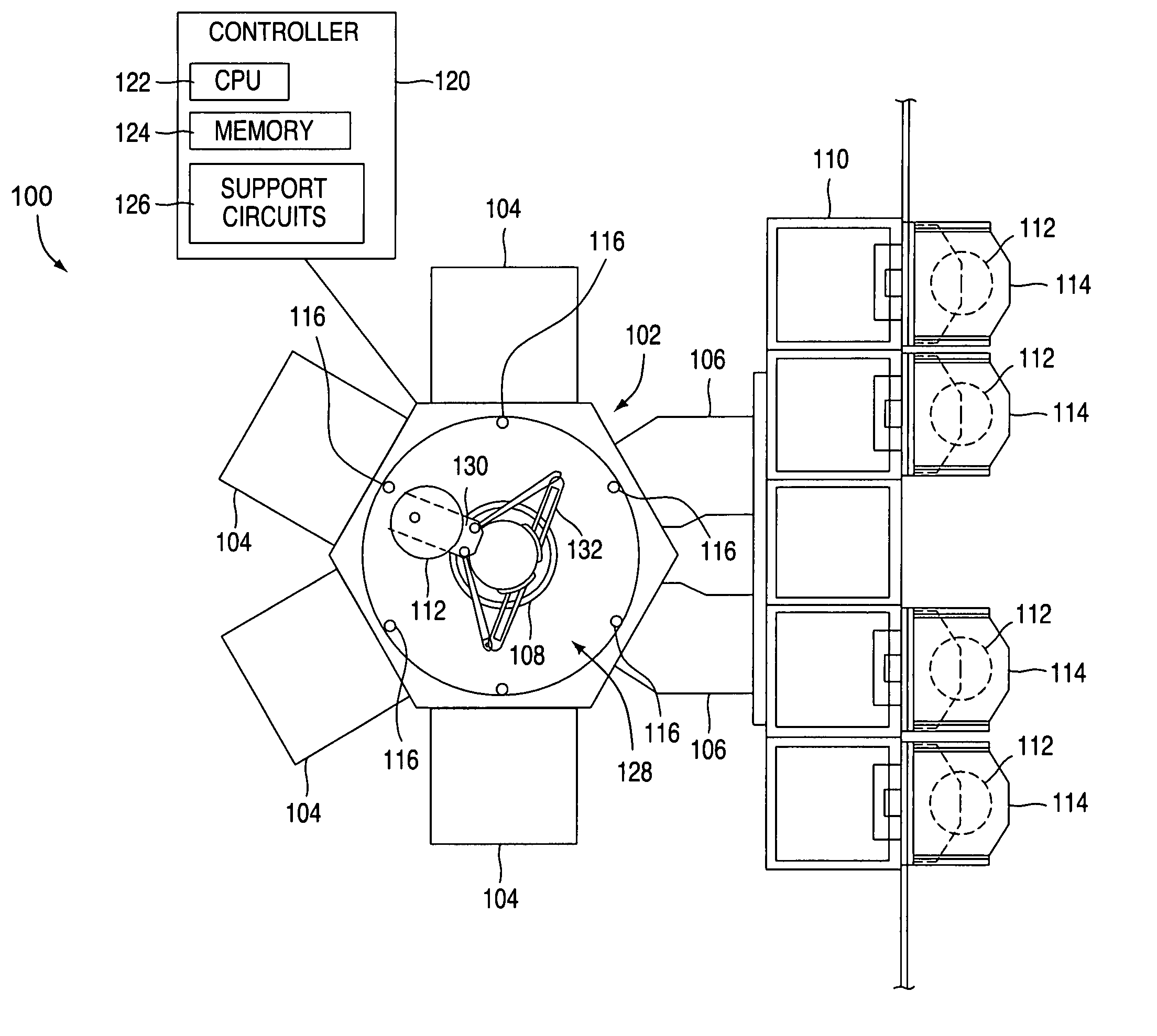
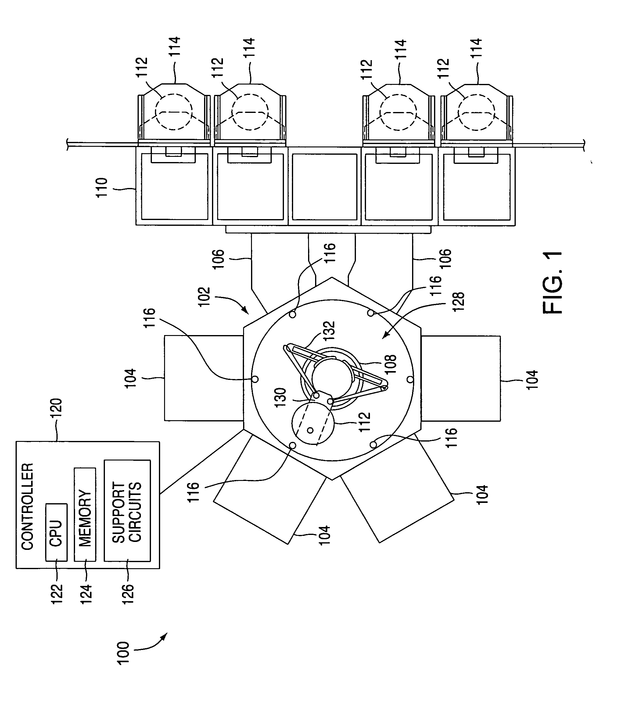
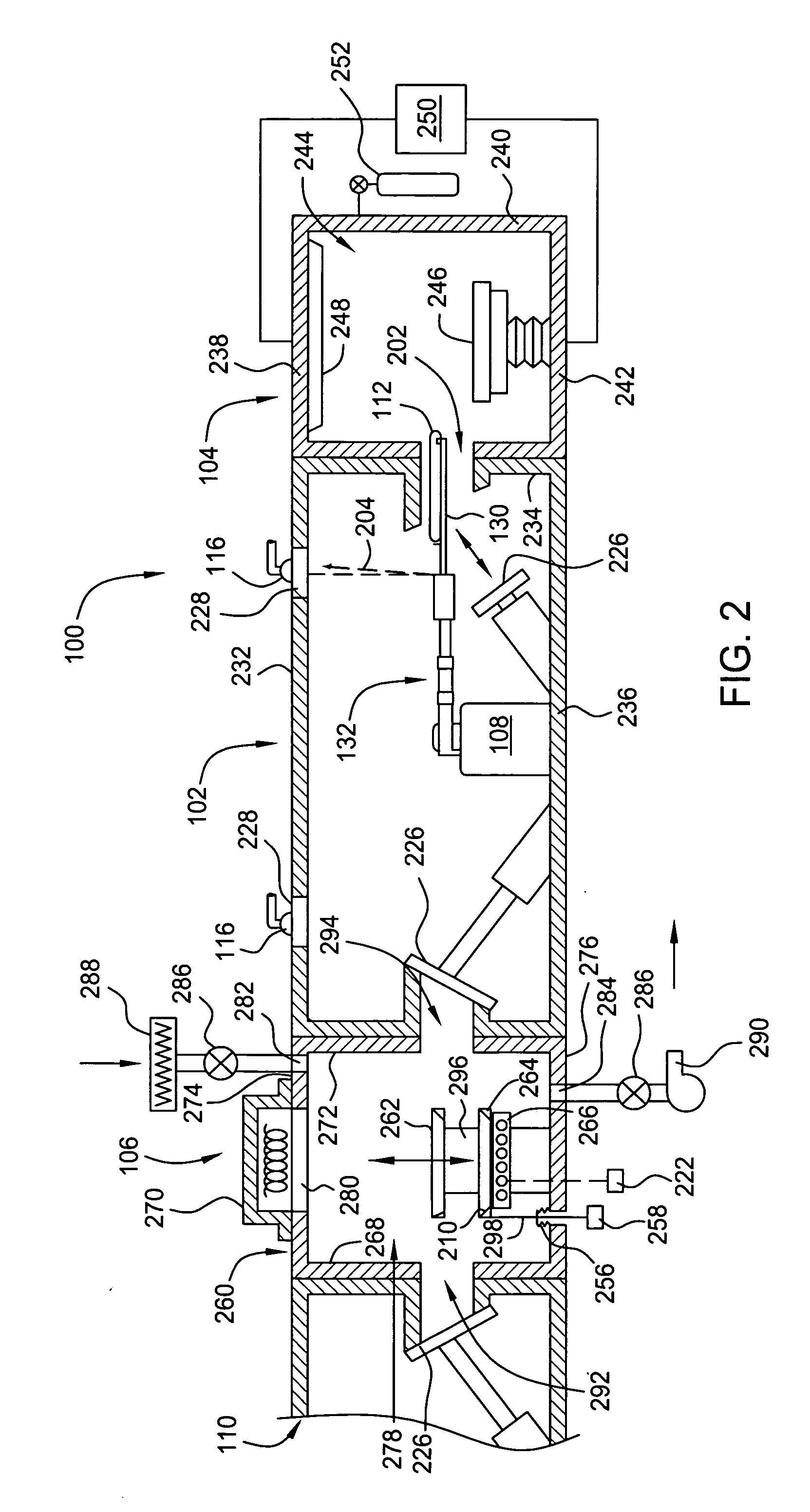
[0035]FIG. 1 depicts one embodiment of a semiconductor processing system 100 wherein a method for determining a position of a robot 108 may be practiced. The exemplary processing system 100 generally-includes a transfer chamber 102 circumscribed by one or more process chambers 104, a factory interface 110 and one or more load lock chambers 106. The load lock chambers 106 are generally disposed between the transfer chamber 102 and the factory interface 110 to facilitate substrate transfer between a vacuum environment maintained in the transfer chamber 102 and a substantially ambient environment maintained in the factory interface 110. One example of a processing system which may be adapted to benefit from the invention is a CENTURA® processing platform available from Applied Materials, Inc., of Santa Clara, Calif. Although the method for determining the position of a robot is described with reference to the exemplary processing system 100, the description is one of illustration and a...


PUM


Abstract

Methods for automated calibration and diagnostics of a workpiece transfer system are provided. In one embodiment, a method for locating an end effector includes retrieving a workpiece located at a target location, passing the workpiece through a plurality of sensors, wherein at least one of the sensors changes state in response to a position of at least one of the end effector or workpiece, recording a metric of robot position associated with the sensor change of state, determining an error for an expected metric of the end effector position from the recorded robot position metric and correcting a taught location of the robot for the target position. In another embodiment, a process for monitoring a robotic transfer system is provided that includes detecting a first positional error in a robotic transfer system, and comparing the first positional error to a second positional error in the robotic transfer system.

Description

CROSS-REFERENCE TO RELATED APPLICATIONS [0001] This patent application claims benefit of U.S. Provisional Patent Application Ser. No. 60 / 572,474, filed Dec. 5, 2003, which is hereby incorporated by reference in its entirety.BACKGROUND OF THE INVENTION[0002] 1. Field of the Invention [0003] The embodiments of the invention generally relate to automated calibration and diagnostics of a workpiece transfer system. [0004] 2. Background of the Related Art [0005] Semiconductor substrate processing is typically performed by subjecting a substrate to a plurality of sequential processes to create devices, conductors and insulators on the substrate. These processes are generally performed in a process chamber configured to perform a single step of the production process. In order to efficiently complete the entire sequence of processing steps, a number of process chambers are typically coupled to a central transfer chamber that houses a robot to facilitate transfer of the substrate between the...

Claims


Application Information

Patent Timeline
Patent Type & Authority Applications(United States)
IPC IPC(8): B25J9/16H01L21/68G06F19/00H01L21/00H01L21/66
CPCB25J9/1692H01L21/67259G05B2219/45032G05B2219/39025H01L21/68H01L22/00
Inventor COX, DAMON KEITHFREEMAN, MARVIN L.
Owner APPLIED MATERIALS INC
Learn More