
Method and apparatus for solving sequential constraints

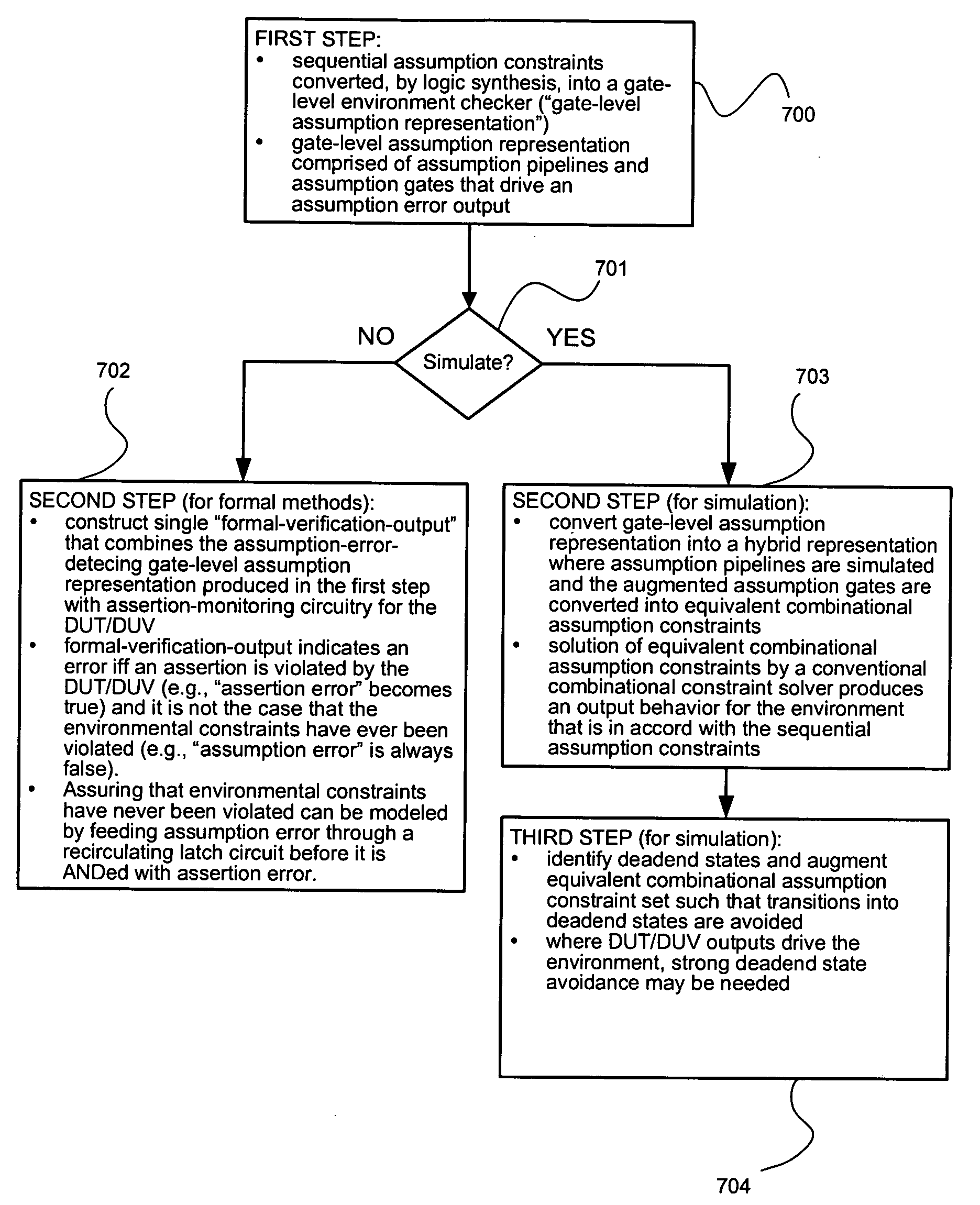
a technology of sequential constraints and methods, applied in the field of solving sets of constraints, can solve the problem that the time-ordered behavior of the environment cannot be specified by the constraints of combinatorial assumption, and achieve the effect of strong deadend avoidance constraints

Active Publication Date: 2005-06-23
SYNOPSYS INC
View PDF19 Cites 18 Cited by
  • Summary
  • Abstract
  • Description
  • Claims
  • Application Information

AI Technical Summary

Benefits of technology

[0066] The above method for deadend avoidance is sufficient if the environment receives no inputs from the DUT / DUV. However, if the environment is subject to variables not under its control, stronger deadend avoidance constraints may be needed.
[0067] In this case, the deadend avoidance method of above can have its augmented deadend states set determined as follows:
[0068] Where N(ŝ,xout,xin,ŝ′) differs from N(ŝ,{circumflex over (x)},ŝ′) by splitting the {circumflex over (x)} into two parts: “xout,” which are outputs of the DUT / DUV; and “xin” which are inputs to the DUT / DUV. The distinction is significant since the “xin” signals are under direct control of the environment while the “xout” signals are not. The above equation is stating that even if there is only one combination of “xout” signals that would cause a transition to a state already a member of a Dk(ŝ), the ŝ should be included in Dk+1(ŝ).

Problems solved by technology

However, combinational assumption constraints cannot specify a time-ordered behavior for an environment since combinational constraints specify assignment of values solely as a functional (or memory less) response to a current state of the various types of inputs that may be applied to it.

Method used


Image

  • Method and apparatus for solving sequential constraints
  • Method and apparatus for solving sequential constraints
  • Method and apparatus for solving sequential constraints

Examples


Embodiment Construction

[0079] Reference will now be made in detail to preferred embodiments of the invention, examples of which are illustrated in the accompanying drawings. Wherever possible, the same reference numbers will be used throughout the drawings to refer to the same or like parts.

[0080] This specification contains pseudo-code to illustrate several embodiments of the invention and to explain its principles. The pseudo-code is loosely based upon the C and C++ programming languages. The C and C++ programming languages are described in such texts as “The C Programming Language”, by B. W. Kernighan and D. M. Ritchie, Prentice Hall, Inc., 1988, ISBN 0-13-110362-8 (paperback), 0-13-110370-9 (hardback) and “The C++ Programming Language,” by Bjarne Stroustrup, Addison-Wesley Pub. Co., 3rd edition, July 1997, ISBN 0-2018-8954-4, which are herein incorporated by reference.

Tabl of Contents to Detailed D scription

[0081] 1. Conversion Of Sequential Constraints [0082] 1.1 First Step [0083] 1.2 Second Step ...


PUM


Abstract

Relates to automatic conversion of assumption constraints, used in circuit design verification, that model an environment for testing a DUT / DUV, where the assumptions specify sequential behavior. Such assumptions are converted, with the use of logic synthesis tools, into a gate-level representation. For formal verification, a verification output is constructed from the gate-level representation and DUT / DUV assertion-monitoring circuitry. A formal verifier seeks to prove the verification output cannot indicate a design error. For simulation verification, the gate-level representation is converted into a hybrid representation comprising pipelines and combinational constraints. During simulation, the pipelines hold state information necessary for a solution, of the combinational constraints, to be in accord with the sequential assumption constraints. For certain sequential assumption constraints, the combinational constraints are insufficient to insure avoidance of deadend states. In a deadend state, an assumption is violated. A method is presented for augmenting the combinational constraints to avoid deadend states.

Description

FIELD OF THE INVENTION [0001] The present invention relates generally to the solution of sets of constraints, and more particularly to the solution of sets of constraints containing at least one sequential constraint, in connection with design verification. BACKGROUND OF THE INVENTION [0002] To tackle the increasing complexity of integrated digital electronic circuits, designers need faster and more accurate methods for verifying the functionality and timing of such circuits, particularly in light of the need for ever-shrinking product development times. [0003] The complexity of designing such circuits is often handled by expressing the design in a high-level hardware description language (HLHDL). The HLHDL description is then converted into a physical circuit specification through processes, well known to those of ordinary skill in the art as “synthesis,” involving translation and optimization. Examples of an HLHDL are: [0004] 1. IEEE Standard 1364-2001, for the Verilog Hardware De...

Claims


Application Information

Patent Timeline
Patent Type & Authority Applications(United States)
IPC IPC(8): G06F9/45G06F17/50
CPCG06F17/504G06F30/3323
Inventor CERNY, EDUARDDSOUZA, ASHVIN MARKHARER, KEVIN MICHAELHO, PEI-HSIN
Owner SYNOPSYS INC
Learn More