System for calibration of gas sensors

a technology for gas sensors and calibration systems, applied in measurement devices, instruments, material electrochemical variables, etc., can solve the problems of low production quantities of these sensors and continue to be very expensive devices

Inactive Publication Date: 2005-06-30
COUNCIL OF SCI & IND RES
View PDF7 Cites 11 Cited by
  • Summary
  • Abstract
  • Description
  • Claims
  • Application Information

AI Technical Summary

Problems solved by technology

The production quantities of these sensors are not very high and they continue to remai...

Method used


Image

  • System for calibration of gas sensors
  • System for calibration of gas sensors
  • System for calibration of gas sensors

Examples


Embodiment Construction

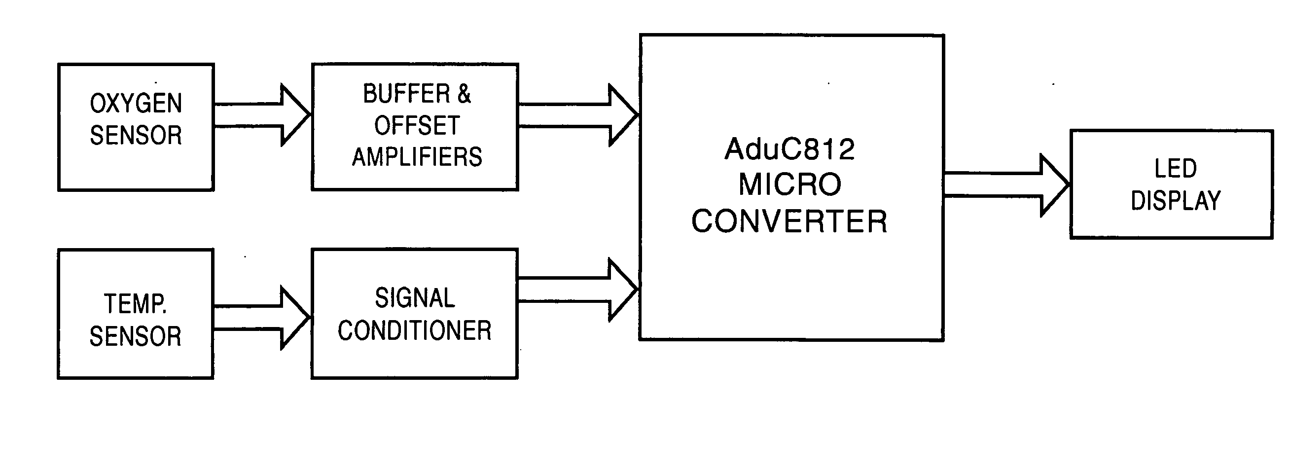
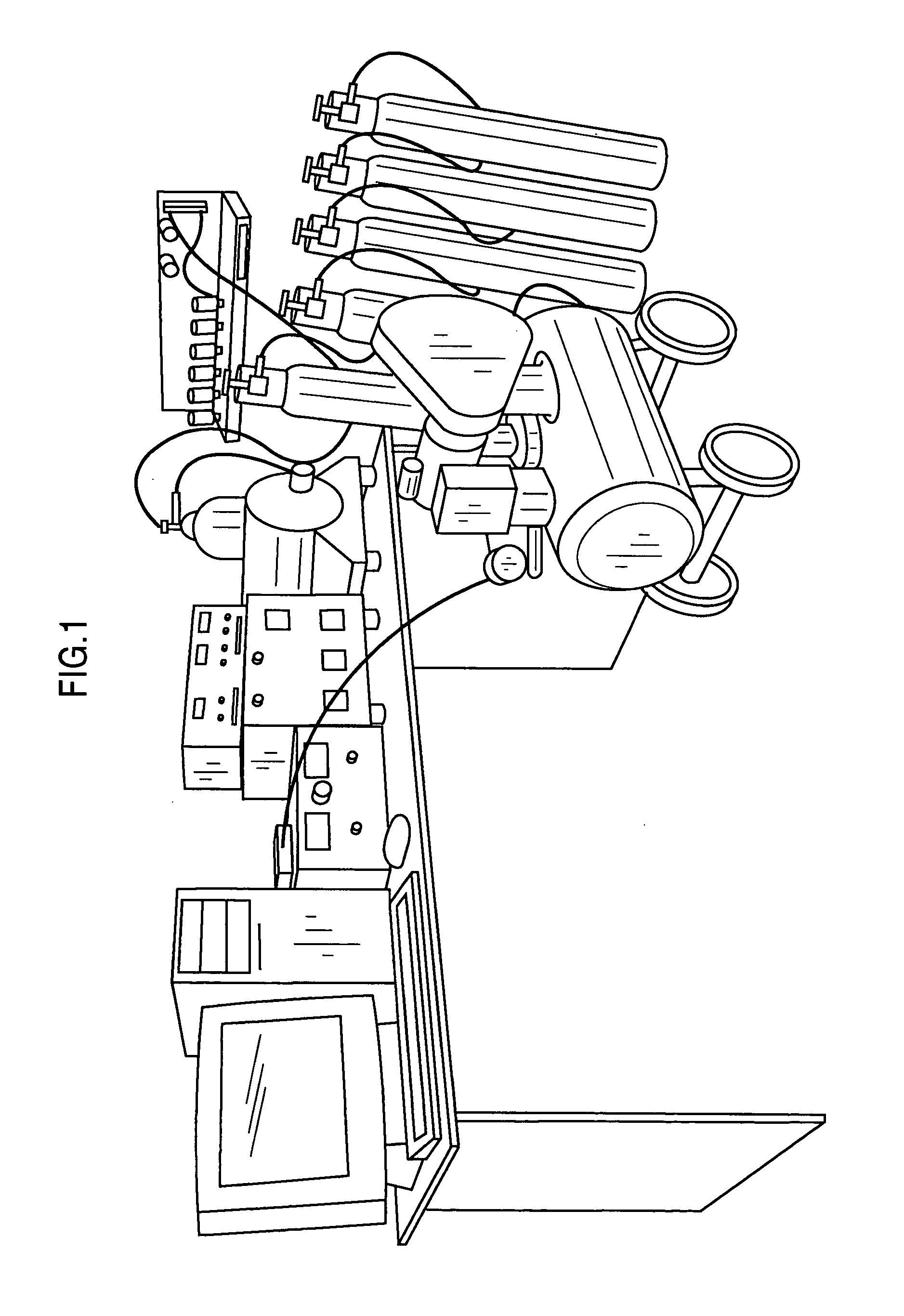
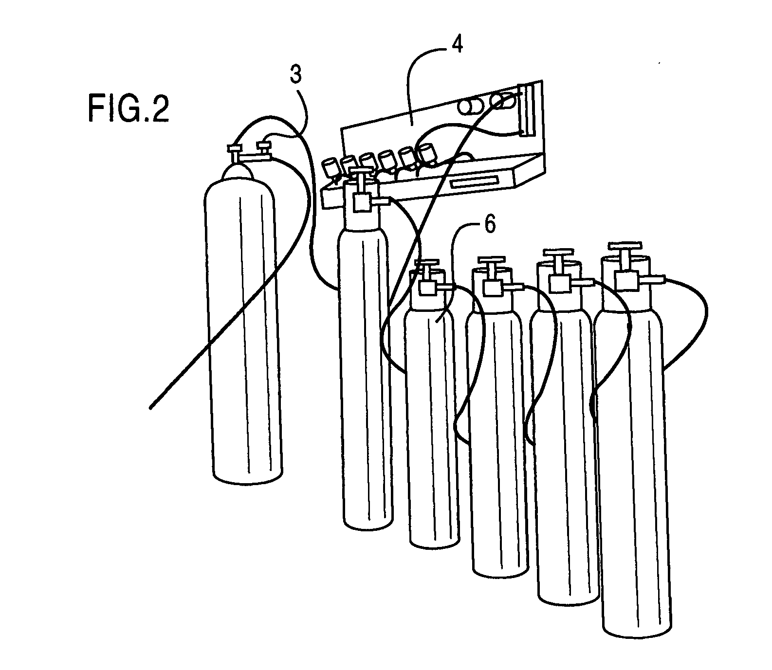
[0025] Accordingly, the present invention provides a system for characterization and calibration of gas sensors, said system comprising: [0026] a muffle furnace attached to a gas selection mechanism, wherein said muffle furnace is being provided with the gas sensor which is to be characterized and a temperature sensor; [0027] the gas selection mechanism supplies a predetermined amount of an air containing a predetermined quantity of the gas to be detected to the muffle furnace; [0028] the gas sensor and the temperature sensors being coupled to a micro converter through a buffer and offset amplifier mechanism and a signal conditioning mechanism respectively; [0029] an output from the micro converter is coupled to a display unit for displaying the values measured by the gas and the temperature sensors.

[0030] In an embodiment of the present invention, the muffle furnace heats the air coming from the gas selection mechanism to a predetermined value to enable the gas sensor to detect an...


PUM


Abstract

The present invention relates to system for calibration of gas sensors and more particularly, the present invention relates to a system for characterization and calibration of bosch zirconium oxide based modified lambda sensors used in oil fired boiler stack gas oxygen measurement.

Description

TECHNICAL FIELD [0001] The present invention relates to system for calibration of gas sensors. More particularly, the present invention relates to a system for characterization and calibration of Bosch zirconium oxide based modified lambda sensors used in oil fired boiler stack gas oxygen measurement. BACKGROUND AND PRIOR ART DESCRIPTION [0002] Modern Automobile Engine Management Systems need a way to monitor the amount of fuel that is injected into the engine while driving on road, off road or on the track. It is a normal practice to introduce the lambda (Oxygen) sensor in the exhaust system for accurate measurement of free Oxygen in exhaust gases. [0003] The Lambda meter or Lambda Display subsystem feeds this Oxygen information to an electronic control unit to adjust the air / fuel ratio to the optimum value for the vehicles fitted with catalytic converters. This subsystem also indicates the air / fuel ratio on the colour coded LED indicators, ranging from rich to lean mixtures, typic...

Claims


Application Information

Patent Timeline
IPC IPC(8): G01N27/26G01N27/417
CPCG01N27/4175
Inventor RAO, REKAPALLI KRISHNAMOHANKOTA, SRINIVASCHANDER, MEENALOCAHNIMOORTHY, D. KRISHNA
Owner COUNCIL OF SCI & IND RES
Why Eureka
Try Eureka