Controller gain scheduling for mass flow controllers

A technology of mass flow and controller, which is applied in the direction of using electric device flow control, flow control, general control system, etc., and can solve problems such as complexity and oscillation

Active Publication Date: 2010-01-27
MKS INSTR INC
View PDF2 Cites 15 Cited by
  • Summary
  • Abstract
  • Description
  • Claims
  • Application Information

AI Technical Summary

Problems solved by technology

The second common control performance problem is oscillation when the set point is changed as shown in Figure 2B
However, this method unnecessarily complicates

Method used


Image

  • Controller gain scheduling for mass flow controllers
  • Controller gain scheduling for mass flow controllers
  • Controller gain scheduling for mass flow controllers

Examples


Embodiment Construction

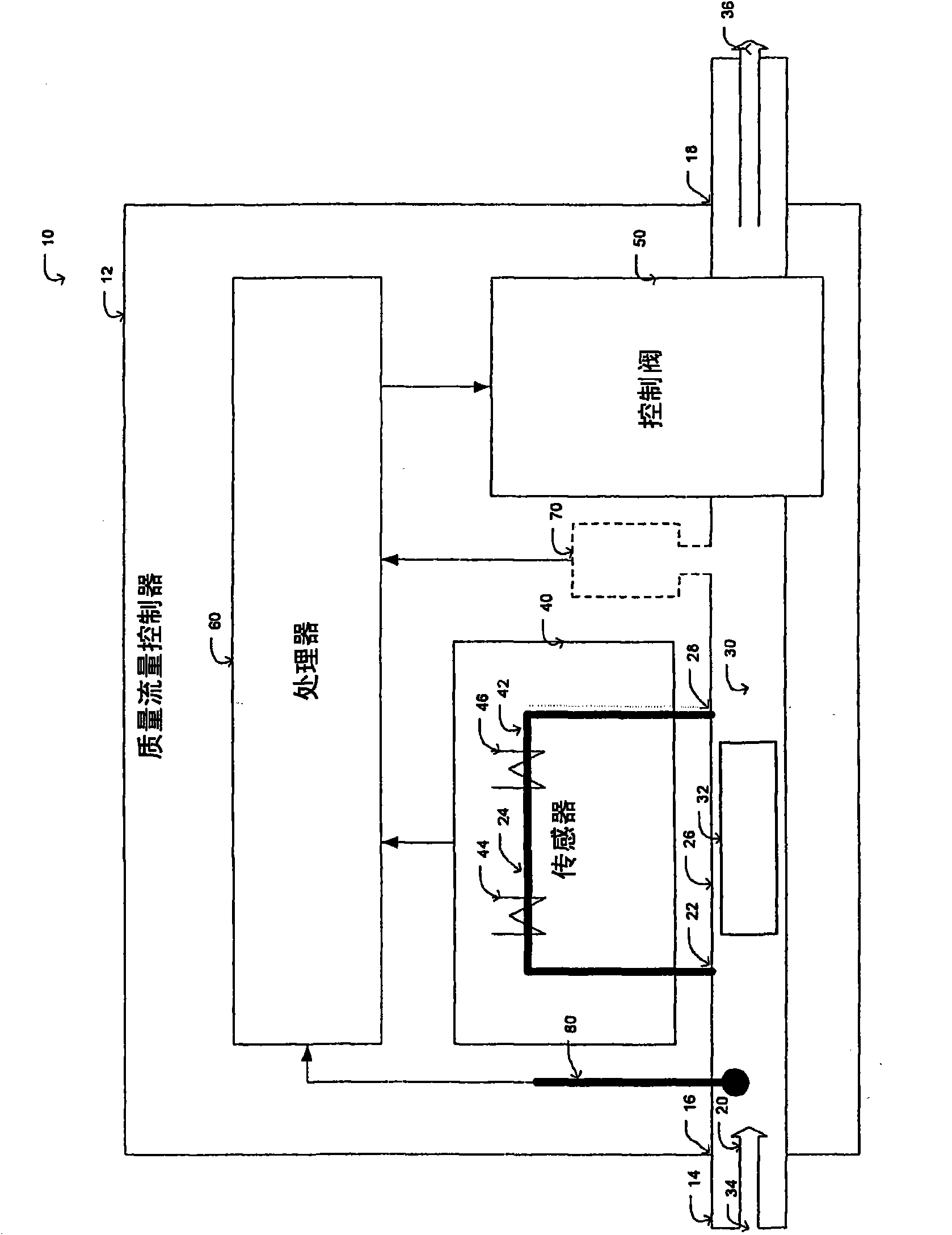
[0018] refer to image 3 In the embodiment shown in , the block diagram of the MFC control system 100 includes a negative feedback control loop. Feedback control systems generally include inputs and outputs, and associations combining the outputs and inputs. In the feedback control loop, Q sp 102 (desired set point flow rate) is input. The obtained actual flow rate Q indicated at reference numeral 116 is an output. In the description below, for example Q(t) and Q sp All time-domain variables of (t) are transformed into such as Q(s) and Q sp (s) Laplacian domain variables, which is a common means used in the control domain.

[0019] The physical model of the control system 100 includes a controller K(s), indicated at 104 , and a valve V(s), indicated at 110 . The feedback controller K(s) generates a control command current I(s) indicated at reference numeral 108 to regulate the opening of the valve such that the output of the valve, the actual flow rate Q(s), tracks the i...


PUM


Abstract

A mass flow controller having a feedback controller gain, comprises: a sensor configured so as to sense the flow of fluid through controller; a valve arranged so as to adjust the flow of fluid through the controller; and a processor configured so as to controlling the valve as a function of the flow of fluid sensed by the sensor. The sensor and valve are arranged within a feedback system, and the processor updates the feedback controller gain in real time based on the ratio of at least one calibration gas parameter to at least one operating gas parameter, such that the closed loop transfer function of the feedback system remains substantially constant regardless of operating conditions so as to have a consistent control performance at different operation conditions from the calibration condition.

Description

technical field [0001] Embodiments of the present disclosure relate generally to measurement and control of fluid flow, and more particularly to model-based controller gain scheduling for mass flow controllers. Background technique [0002] A mass flow controller (MFC) is a device that sets, measures and controls the flow rate and amount of a fluid, such as gas or steam, flowing through the device. These devices are designed and calibrated to control airflow over a predetermined range of flow rates with high precision. [0003] Some manufacturing processes, such as for semiconductor manufacturing, require precise control of the flow rate and quantity (quality) of gases or vapors delivered to process chambers or tools. Often, precise fluid flow rates and volumes (total mass of fluid) are critical to ensure optimal results. Applications include the metering of precise quantities of gas or vapor into the process chamber for subsequent sputtering on workpieces, dry etching to ...

Claims


Application Information

Patent Timeline
Patent Type & Authority Applications(China)
IPC IPC(8): G01F1/68G01F15/00G01F25/00G05B13/04G05D7/06
CPCG01F1/68G01F15/005G05D7/0635G05B13/042G01F25/0007Y10T137/7759Y10T137/7761G01F25/10G01F15/00G01F25/00G05B13/04
Inventor 丁军华
Owner MKS INSTR INC
Why Eureka
Try Eureka